
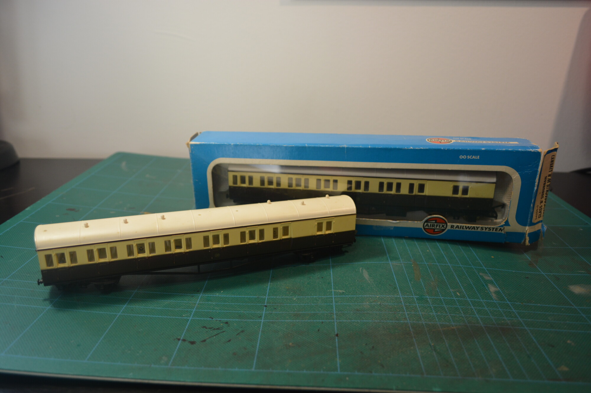
This is the first of two articles covering my upgrade of a pair of Airfix GWR “B-set” suburban coaches. These models pre-date me by a decade or so (they have 1975 written on the underside) and were given to me a long time ago. They were probably my first “complete” passenger train, as most of the stock I had when I was younger was the typical hodge-podge of second-hand wagons and carriages picked up at model shows.
The Airfix effort was a decent model for the time (the glazing stands out as pretty good for 50 years old!), but they’re now showing their age in a few areas. Last year I found an excellent video on the Steam With a Scooby Youtube channel that shows a B-set upgrade, so I thought I’d do the same.
This upgrade will be in two parts:
- In part one, I’ll fit new bogies, all new underframe detail, close-coupling mechanisms and buffers, and also paint the interiors and parts of the bodies.
- In part two, I’ll be fitting working lighting to the coaches. Depending on the progress of another project, this may or may not include the use of custom-made DCC decoders to control the lighting.
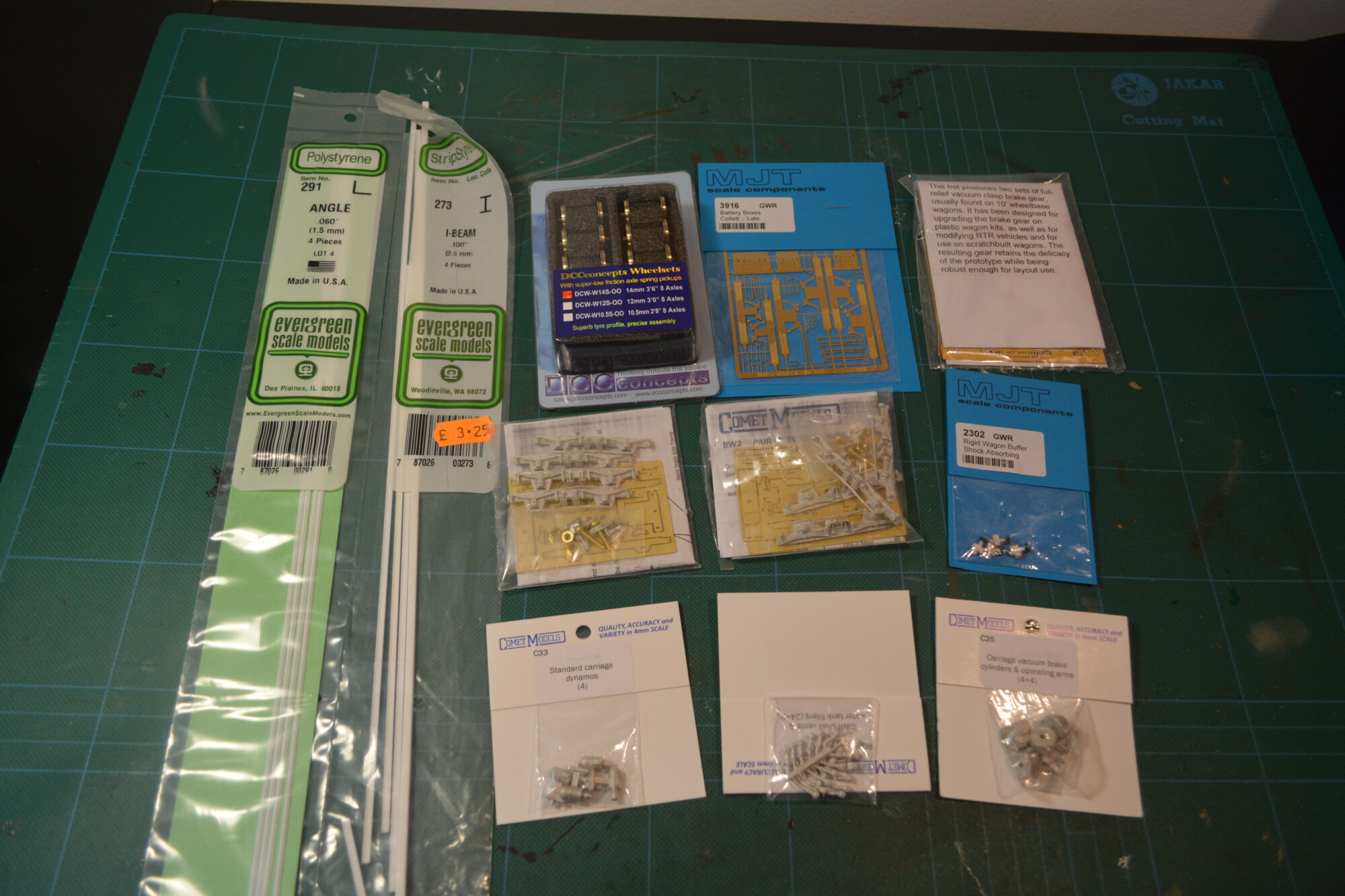
Shopping list
The shopping list for this part of the project was as follows:
| Item | Manufacturer | Seller | Price |
|---|---|---|---|
| BW2 GWR 7′ Plate Bogies | Comet | Wizard models | £17.00 |
| RC5 GWR Airvents | Comet | Wizard models | £2.50 |
| C35 Vacuum Cylinders | Comet | Wizard models | £3.90 |
| C33 Dynamos | Comet | Wizard models | £3.90 |
| MT234 V Hangers etch | Mainly Trains | Wizard models | £4.00 |
| 3916 GWR Battery Boxes | Frogmore | Dart Castings | £4.20 |
| 2302 GWR Shock absorbing wagon buffers | MJT | Dart Castings | £4.40 |
| 111 Close-coupling mechanism | Symoba | Symoba | £8.00 |
| 1.5mm angle strip styrene | Evergreen | eBay | £1.50 |
| 1mm plastikard | Slaters | eBay | £0.50 |
| DCW-W14S-OO Pack of 14mm dia. wheelsets | DCC Concepts | Hattons | £21.50 |
| 4MA071 Shouldered bearings | Markits | Stenson models | £3.75 |
| 1x 0.45mm / 0.7mm Brass wire | Various | eBay | £1.00 |
| Total | £76.15 |
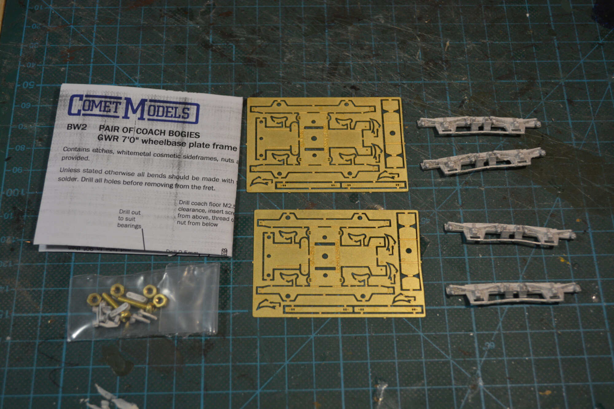
Bogies
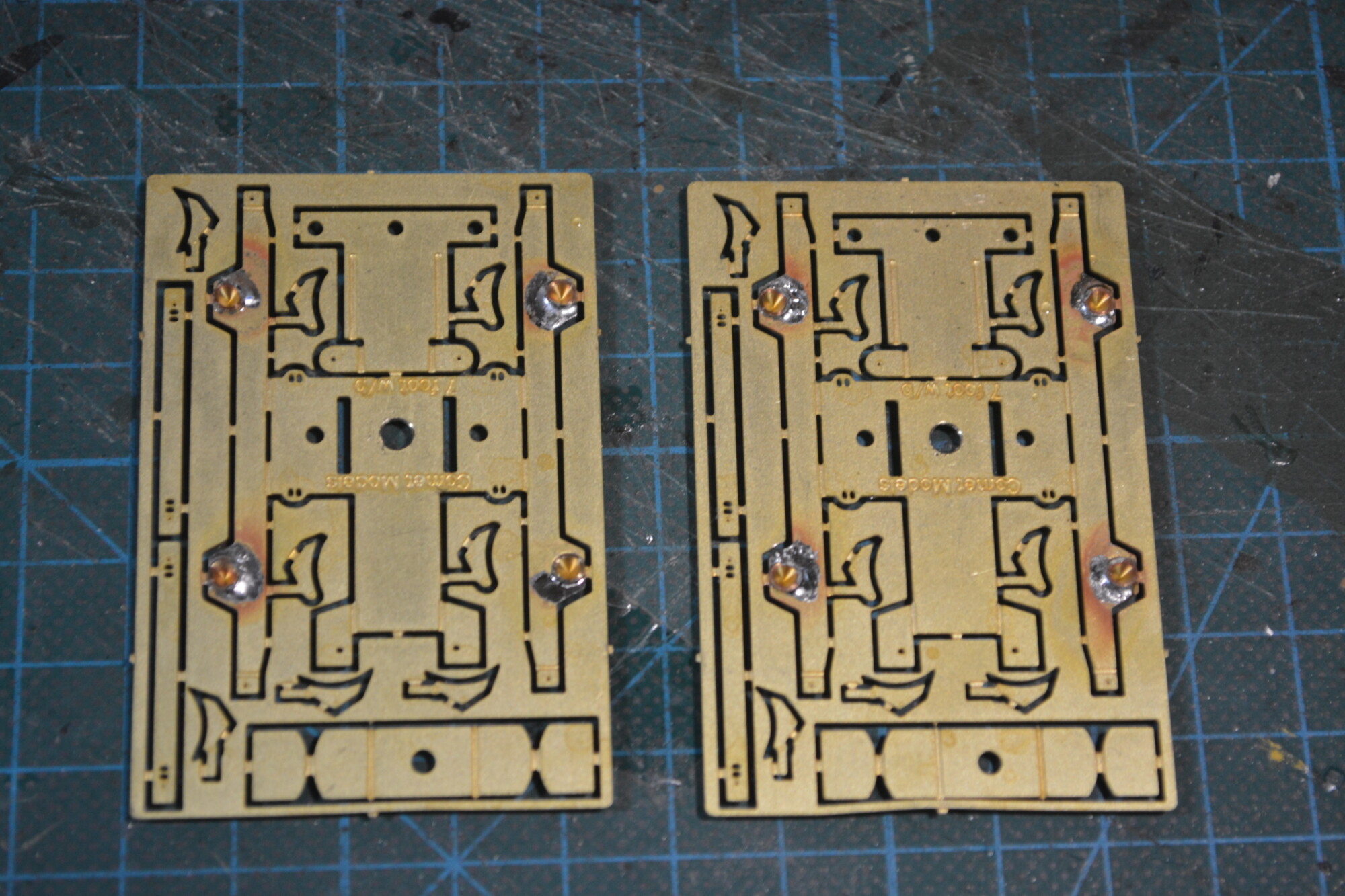
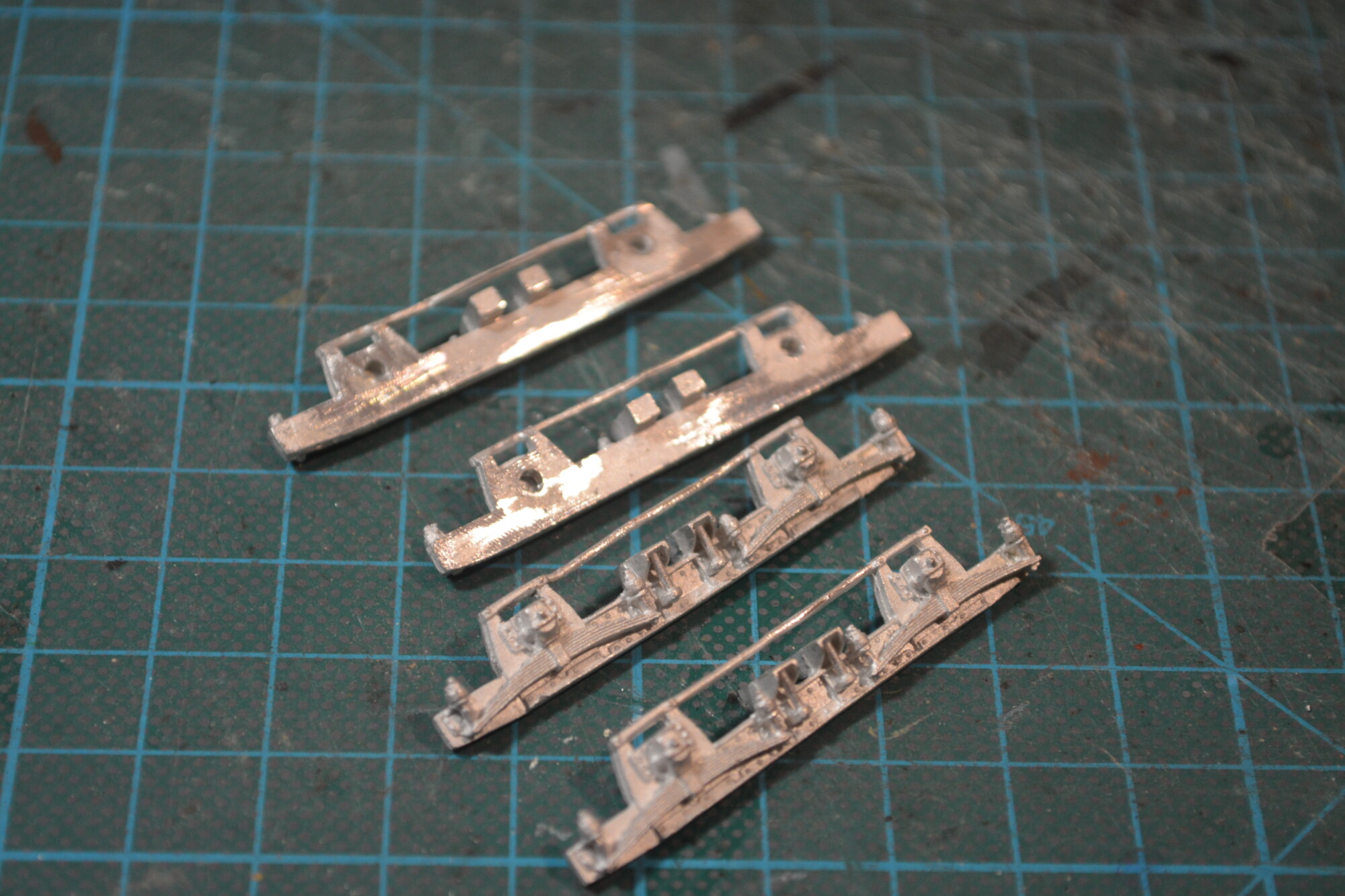
I started with the bogies. These are supplied two to a pack, with an inner structural frame made from etched brass, which is then faced with a pair of decorative white metal side pieces.
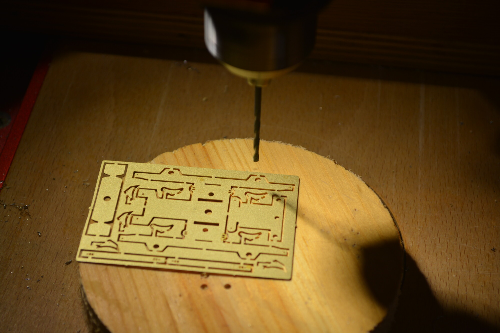
I began by opening up the holes for the bearings to 2mm, to allow room for the Markits bearings to fit.
I then fitted the bearings to the frames whilst they were still attached to the fret. This meant I could hold the outer frets in the jaws of my helping hands, thus reducing the chance of damaging the frame itself. I used flux around the outside of the bearing, to help guide the solder down to the brass sheet, rather than up and into the bearing. I’ve had solder flood bearings before, and it’s a pain, and basically means the bearing is useless and has to be thrown away.
The sides of the frames were then removed from the frets (along with the other components) and the edges folded up.
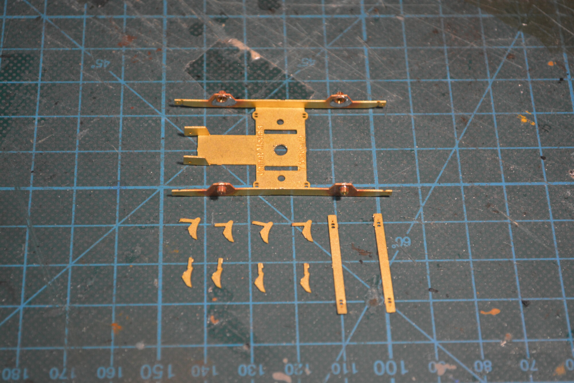
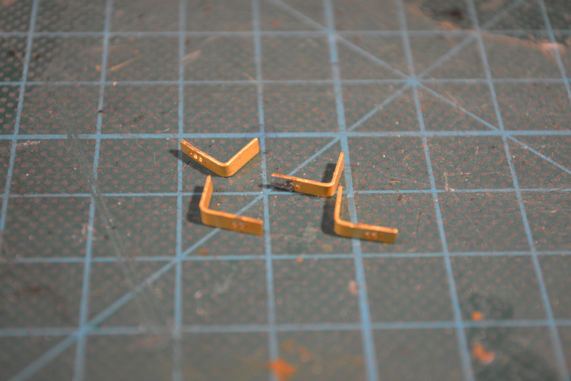
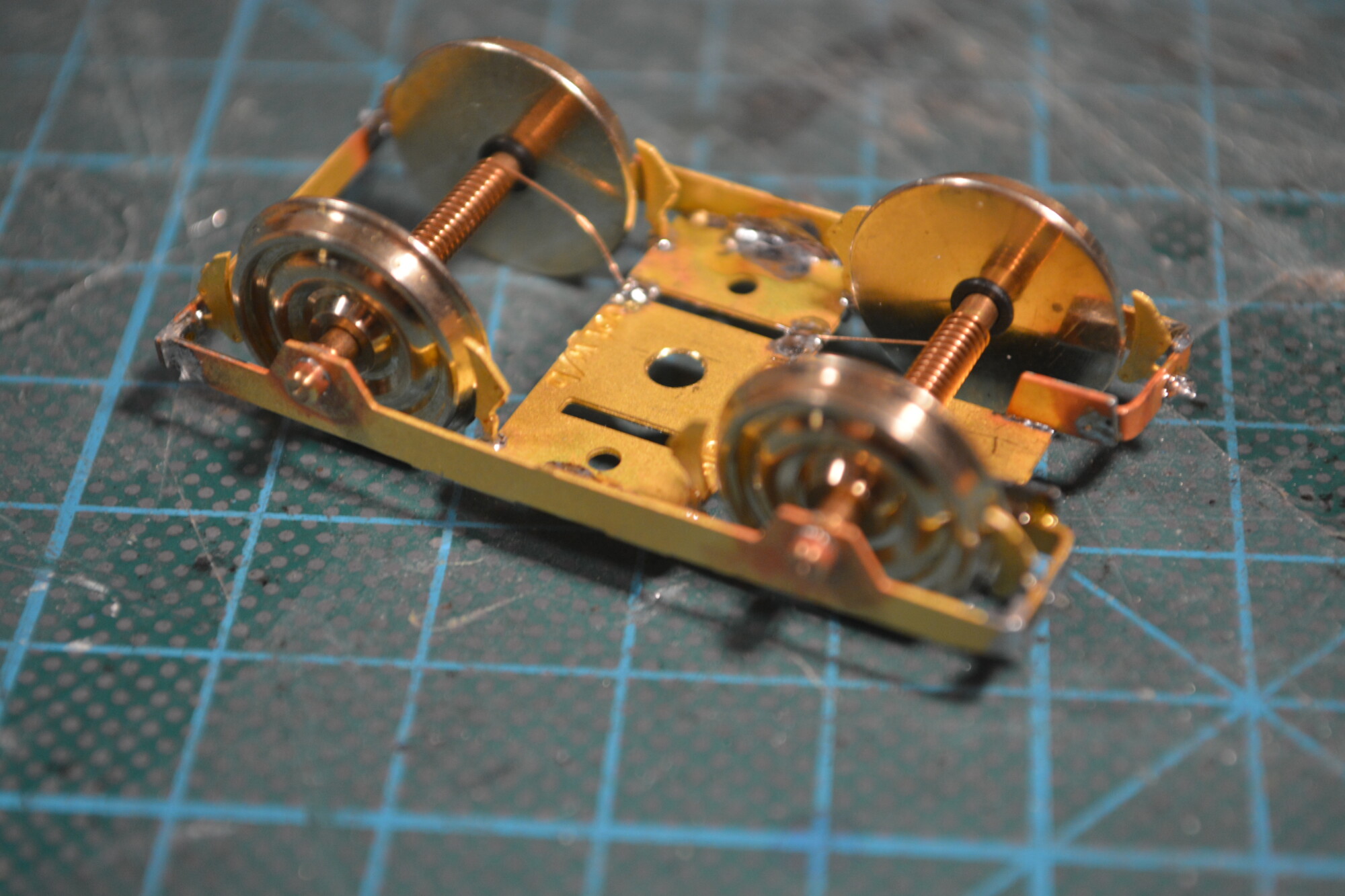
At this point I realised I would have to modify the bogies slightly – instead of the stretcher bar (cross piece) at the “outer end” going straight across, it would need to have a break in the middle to allow space for the close coupling mechanism to sit. I therefore cut the stretcher bars in half and put a 90-degree bend in them.
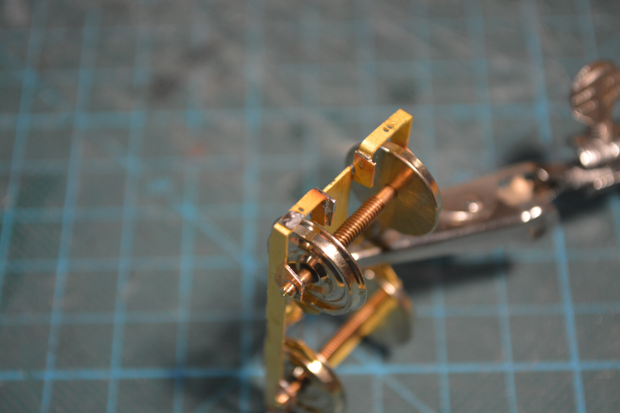
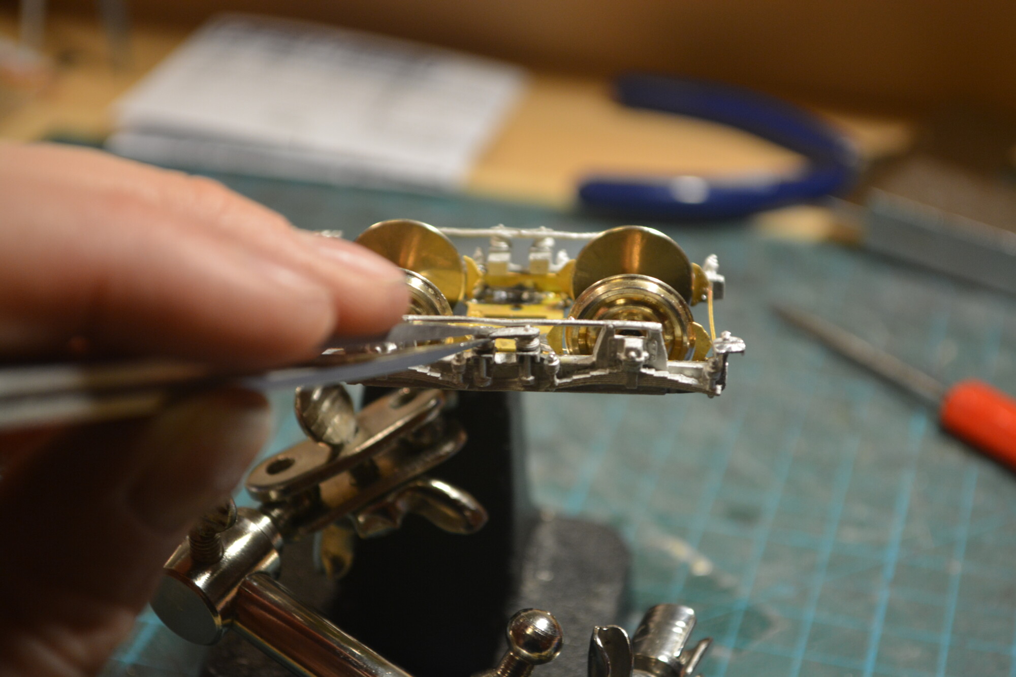
The wheels could then be fitted and the frame could be assembled. I took my time with the distance between the sides, in order to get the axles to sit perfectly in the bearings with mimimal side-to-side movement. I did this by soldering the stretcher bars on, checking for movement, and then adjusting by heating the joint again and quickly moving the pieces relative to each other a fraction, and then testing again. This process was repeated until the axles barely move from side to side (they have perhaps 0.25mm of movement), but spin nice and freely.
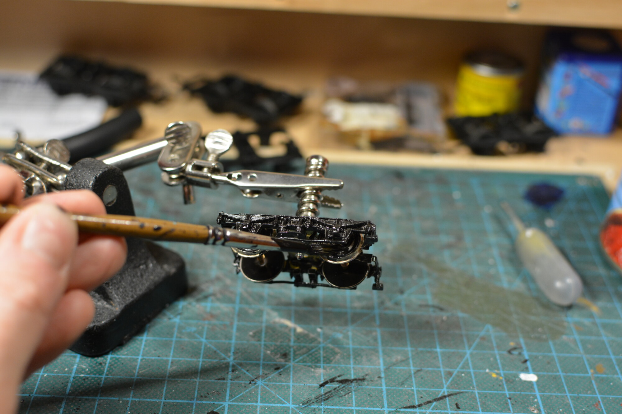
Next to be fitted were the brake shoes. There were eight of these per bogie, and they were rather fiddly! I ended up doing them by first soldering them in roughly the right place, and then adjust them with tweezers whilst heating the solder joint to loosen it up. I aimed to get each shoe about 1mm from the wheel. At roughly 100mm full-scale, this is a larger gap than would be typical on the prototype, but I wanted to make sure there was no chance of the shoes rubbing on the wheels and causing issues.
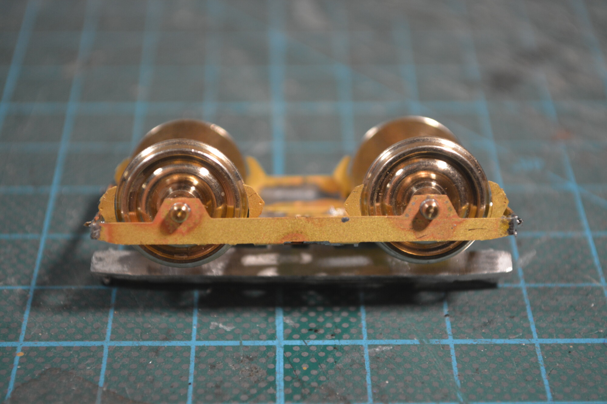
The DCC Concepts wheelsets come pre-fitted with copper springs on the axles for pick-up from the track. Since the entire bogie is brass, I simply soldered the ends of these springs to the frame. I’ll then run a wire from each bogie up into the body of the coach. Depending on how noisy these springs are (sometimes then can cause an annoying squeak when running), I might remove them entirely and rely on the continuity between the axles and the brass bearings. This approach worked well on my FEA wagons.
It was then time to fit attach the decorative bogie sides. This was my first time working with white metal kits, and I immediately ran into one of the issues with them – the components can often be bent and deformed. Luckily this wasn’t too hard to correct, as the pieces could be gently bent back into shape by pressing them by hand against a hard flat surface.
Before the frames could be attached, I very carefully opened up the holes for the bearings with a 2.5mm drill bit in a hand chuck. I chose 2.5mm as this gave me 0.5mm spare on each, which was necessary because the holes in the outer frames didn’t quite line up with the bearings in the inner frames.
Finally I filed the inside of the frames to remove the last dips and bumps left over from straighening them earlier. This helped the frames sit a little snugger on the inner frames.
The sides are soldered to the brass inner frames using drop of solder are various points all around the piece. I had to be careful not to melt the white metal, and a couple of times it did deform when the iron got too close, or the heat was applied for a bit too long. These bits were in hidden areas though, so it was all good.
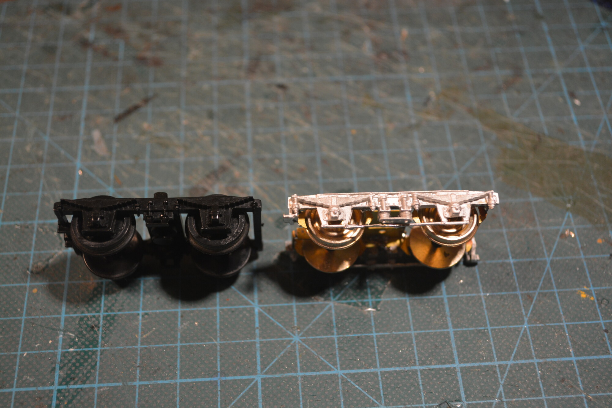
The bogies took a while to assemble – probably six hours in total for all four – but they look great. Below is a comparison to the original plastic bogie. Whilst the white metal ones aren’t perfect (modern plastic ones would be more detailed and wouldn’t suffer from the deforming issue), they’re still a big upgrade. Plus they have a fair amount of weight to them, which will help the coaches run better on the rails.
Painting the bogies was a pretty straightforward process – a base coat of all-purpose primer was applied and allowed to dry overnight.
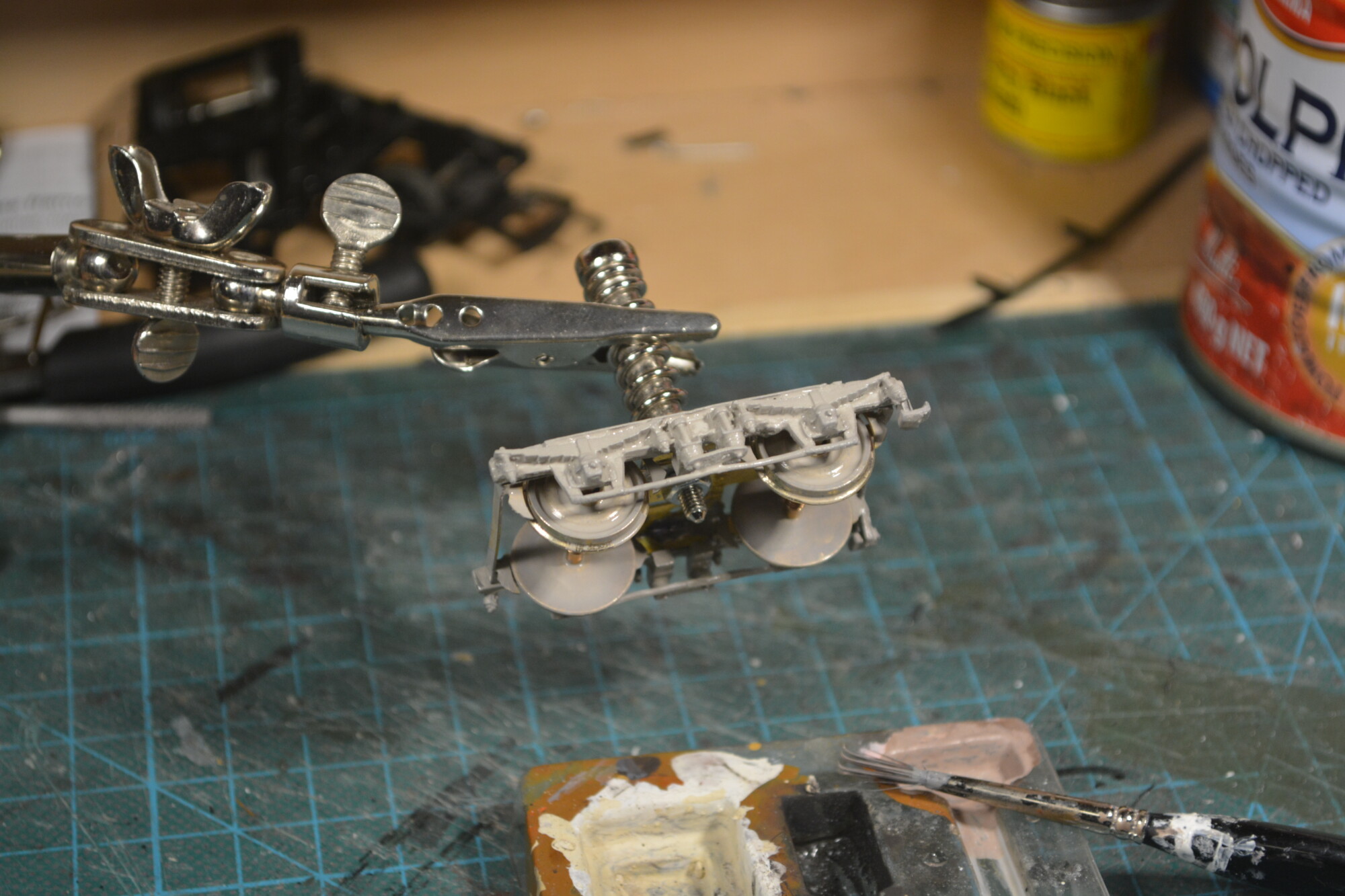
I went for a semi-gloss black for the top coats, mainly because this is what I had in my paint box! It actually turned out pretty well, considering it was just a tin of all multi-surface paint I got for free from my neighbour!
Chassis
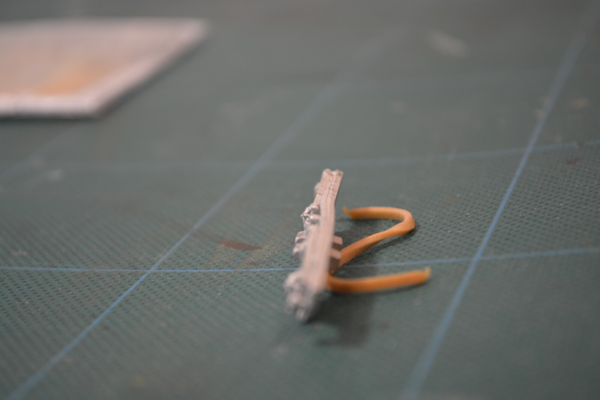
The next major part to tackle was the chassis itself. Following the SWaS video, I removed all underframe detail with a Dremel and cutting disc. This included the buffer beams, as they are incorrectly curved on the Airfix model.
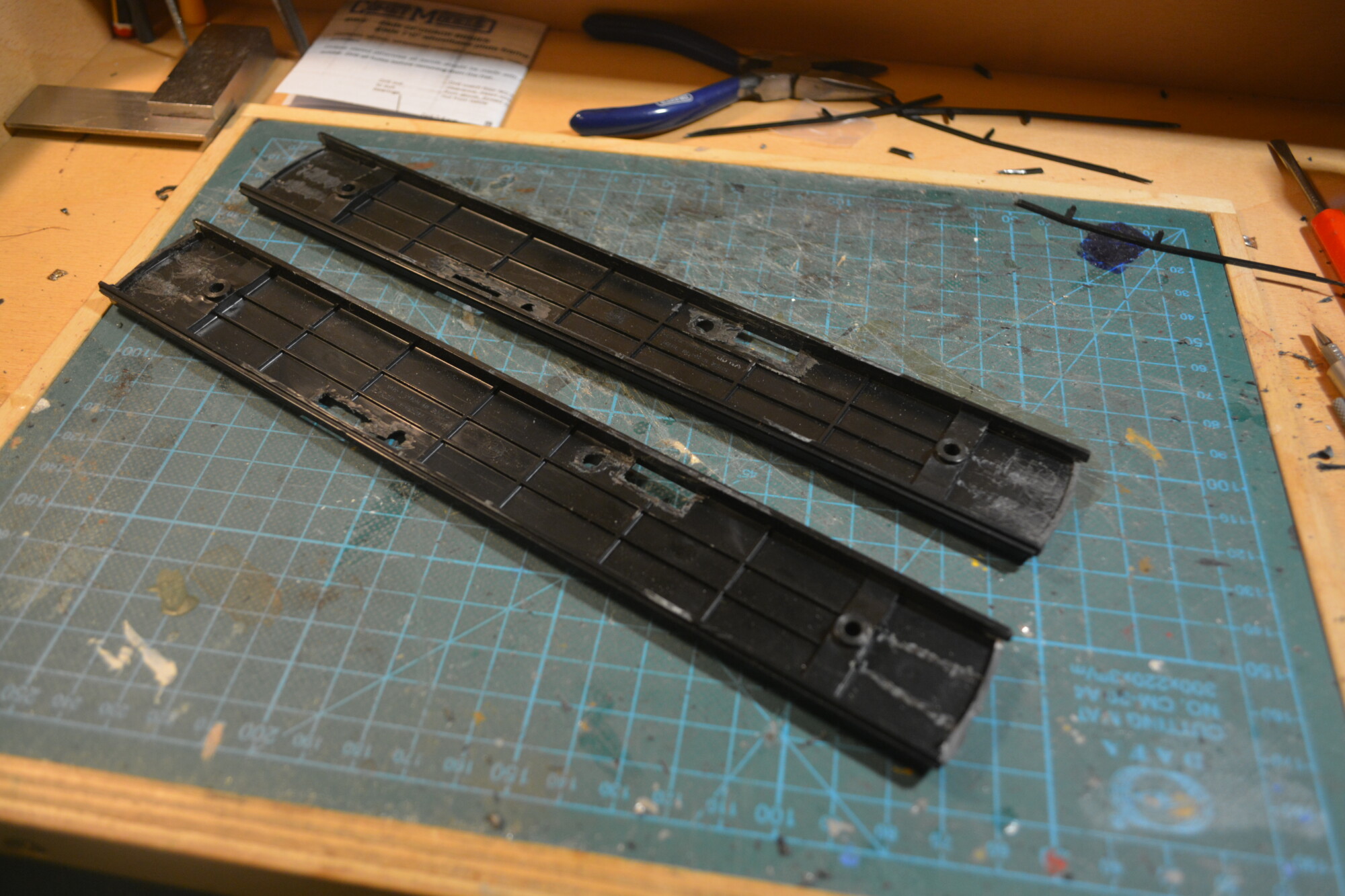
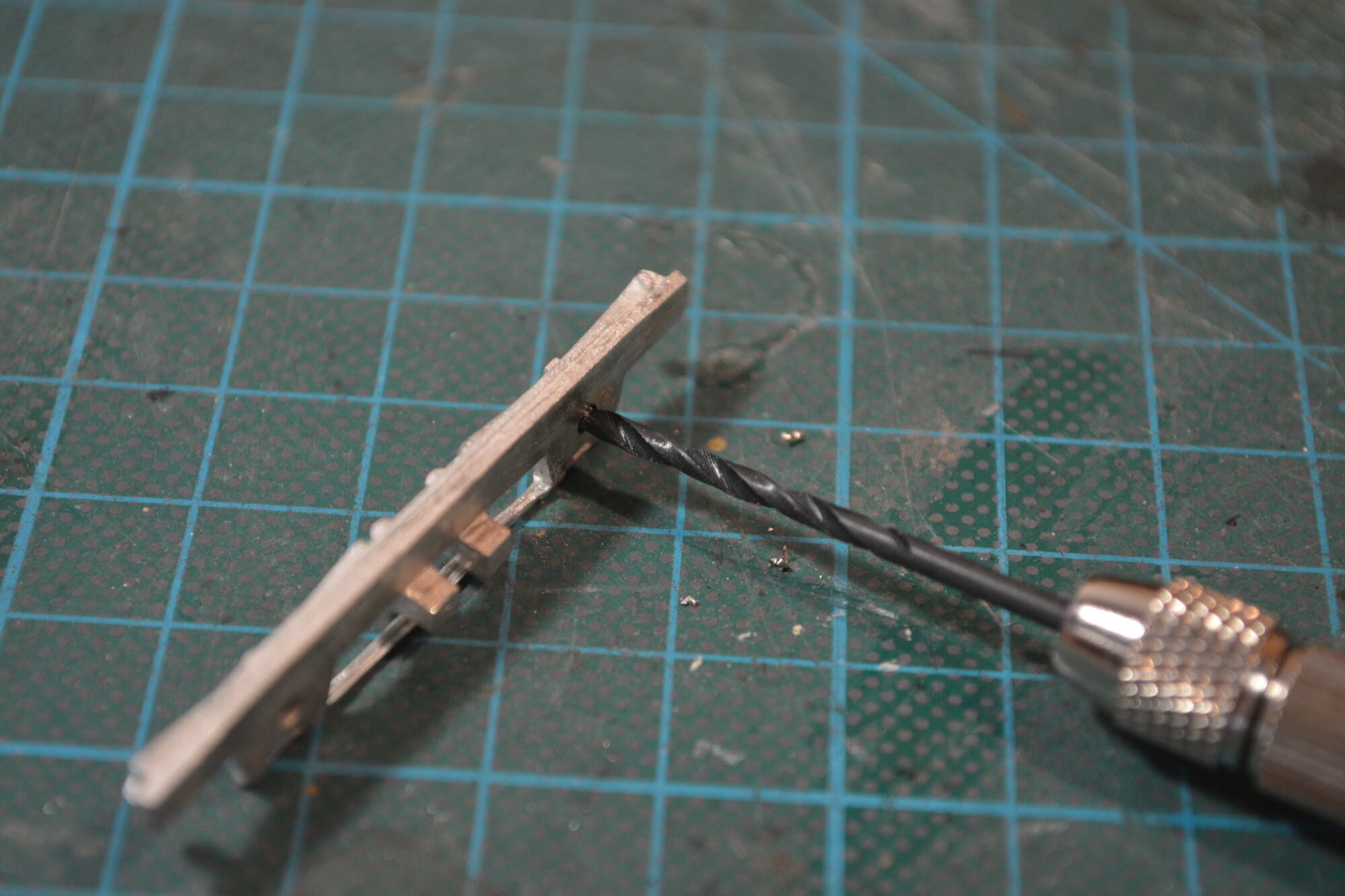
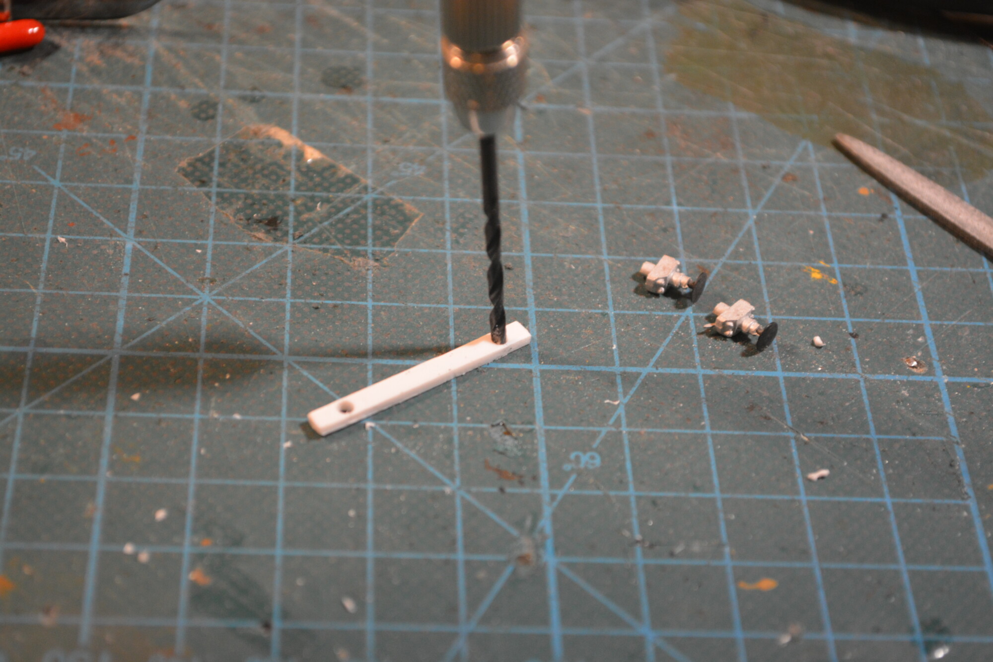
The replacement buffer beams were made up from some 1.5mm think plasticard that I cut to an appropriate thickness to match the rest of the chassis sides. I then drilled a pair of holes to locate the buffers. I did this for all four buffer beams, even though I do not have any buffers for the outer ends yet, as drilling holes will be easier at this stage.
The replacement buffer beams were then glued in place with polystyrene cement. To help align them correctly, I fitted the chassis into the bodyshell before glueing.
Battery boxes
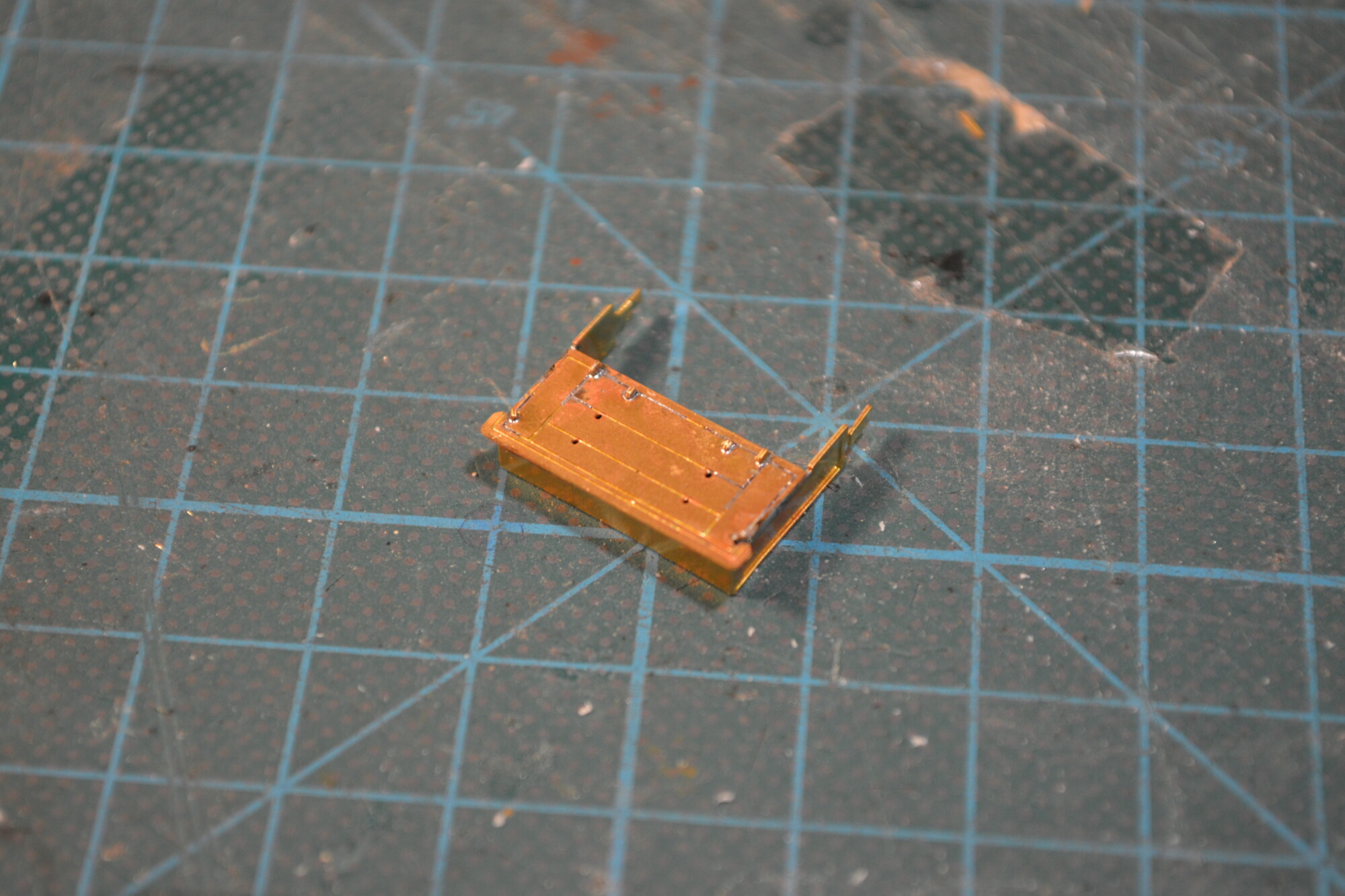
These lovely kits are from Frogmore, and comprise two main parts: the front and top, and a wrap-around side piece that also makes up the bottom. The kit doesn’t really come with any instructions, but as SWaS found, the internet provided the answer as to how they go together.
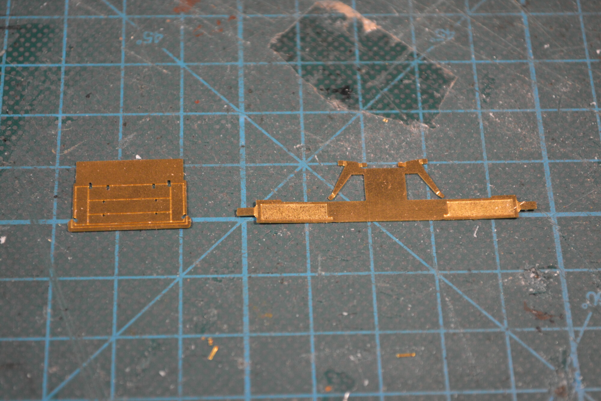
The first job is as always to remove them from their frets and remove any burrs. I then bent up the various small horns that will be used to hold the thing together during assembly. Going by the “odd” arrangement of the horns, I’m guessing that the horns also function as decorative features, representing hinges and catches on the front of the battery boxes.
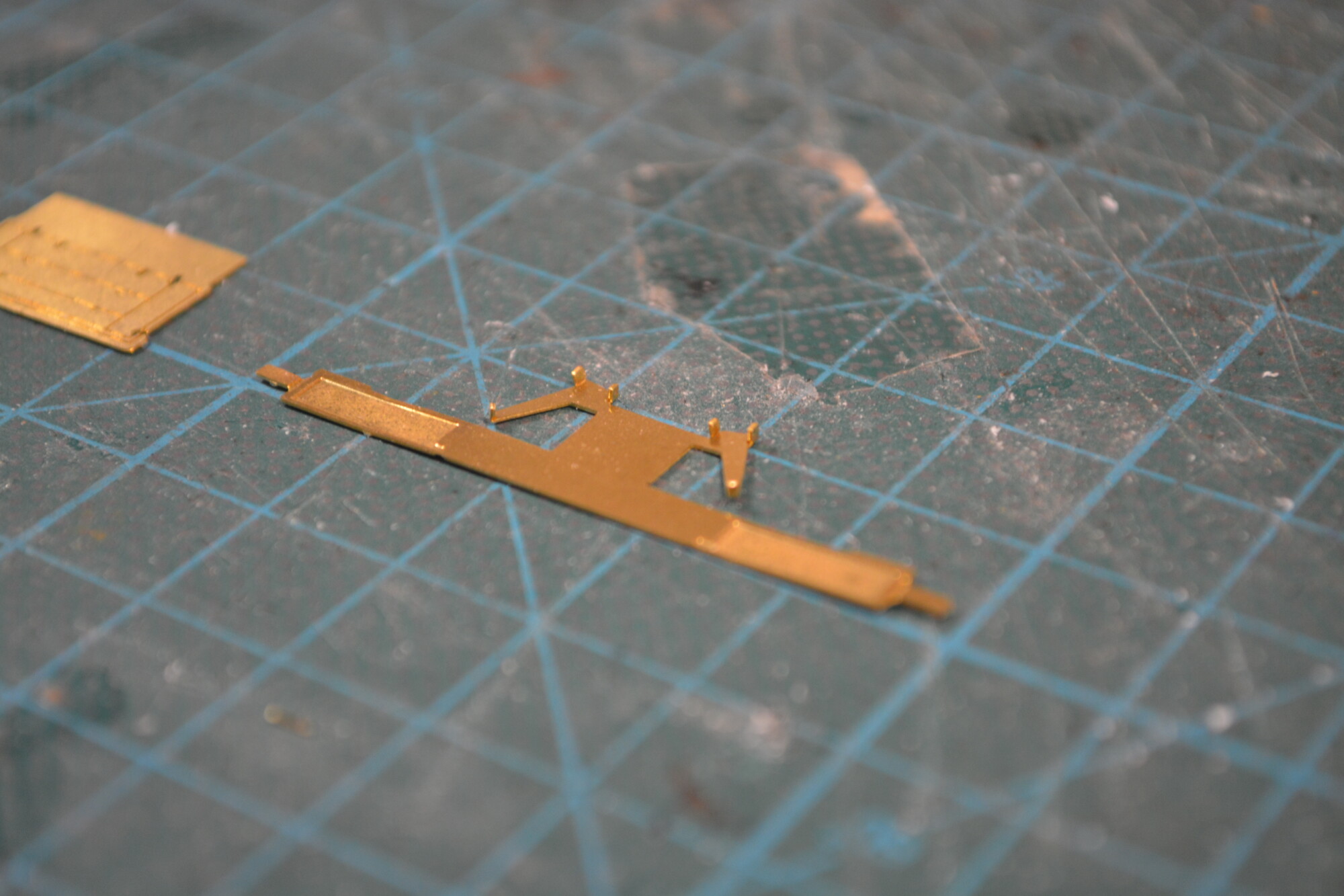
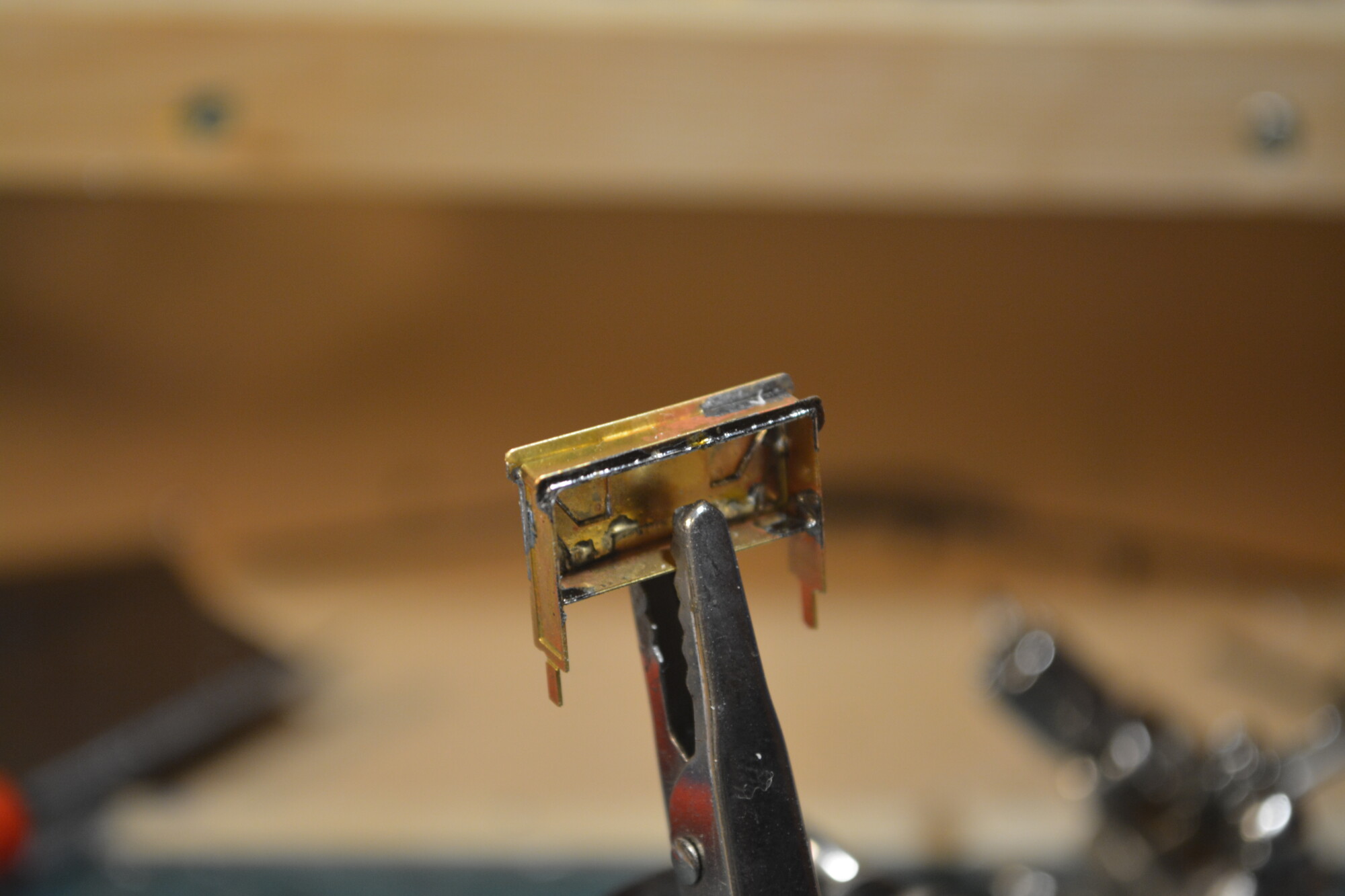
Next, I joined the two pieces together by inserting the horns through the corresponding holes in the front piece. Due to their arrangement, there is only way the two pieces can fit together. I applied some flux to the join and soldered to complete the join. One my first attempt, I used too much solder and some of it flowed through the holes and into the nicely-etched grooves, thus spoiling the look a bit, but I learned my lesson for the remaining boxes.
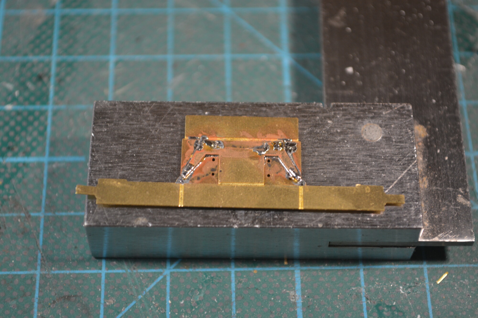
Next, I bent the bottom and side piece up by 90 degrees.
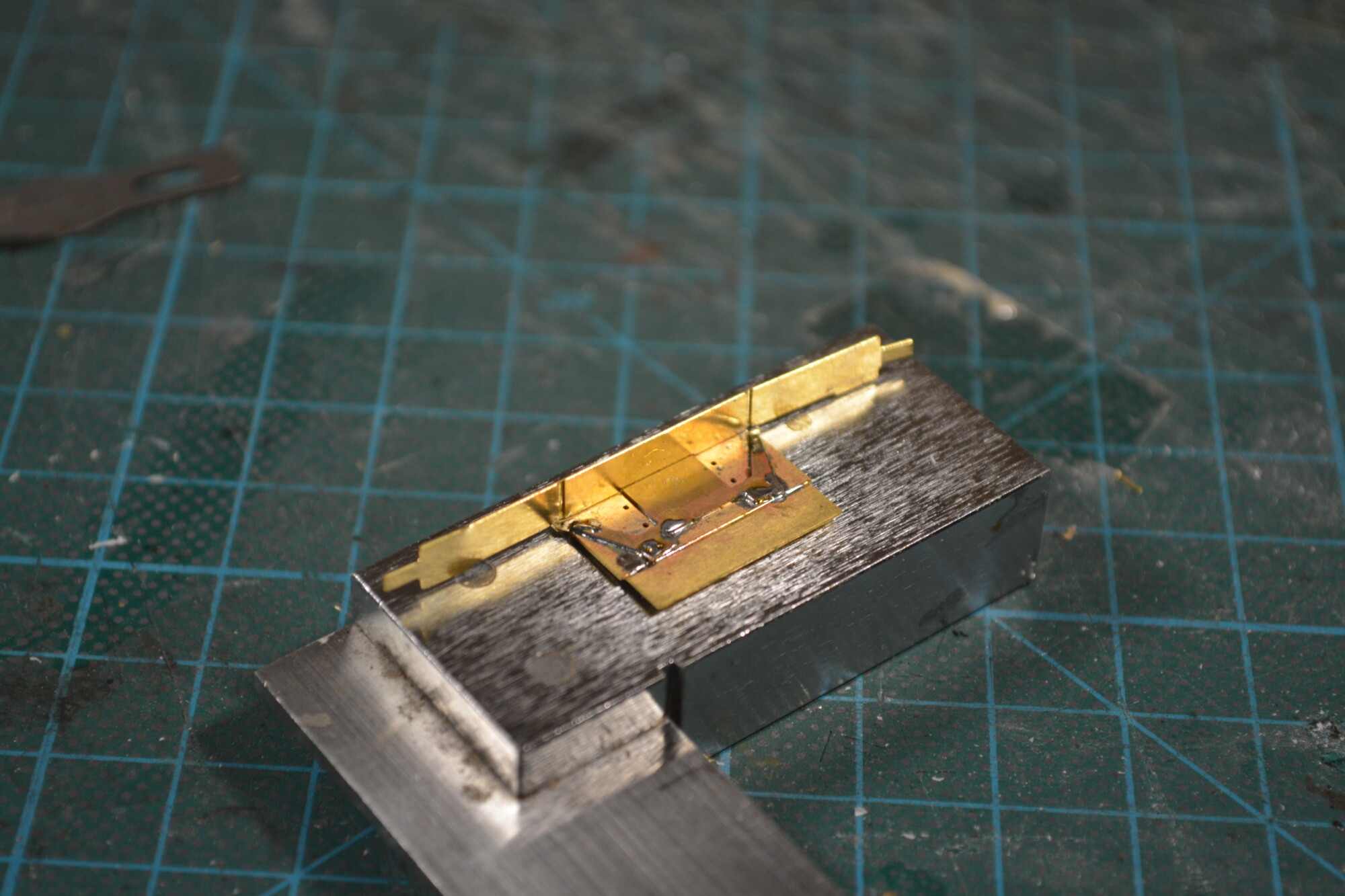
I then folded the sides up, again by 90 degrees, and soldered them in place.
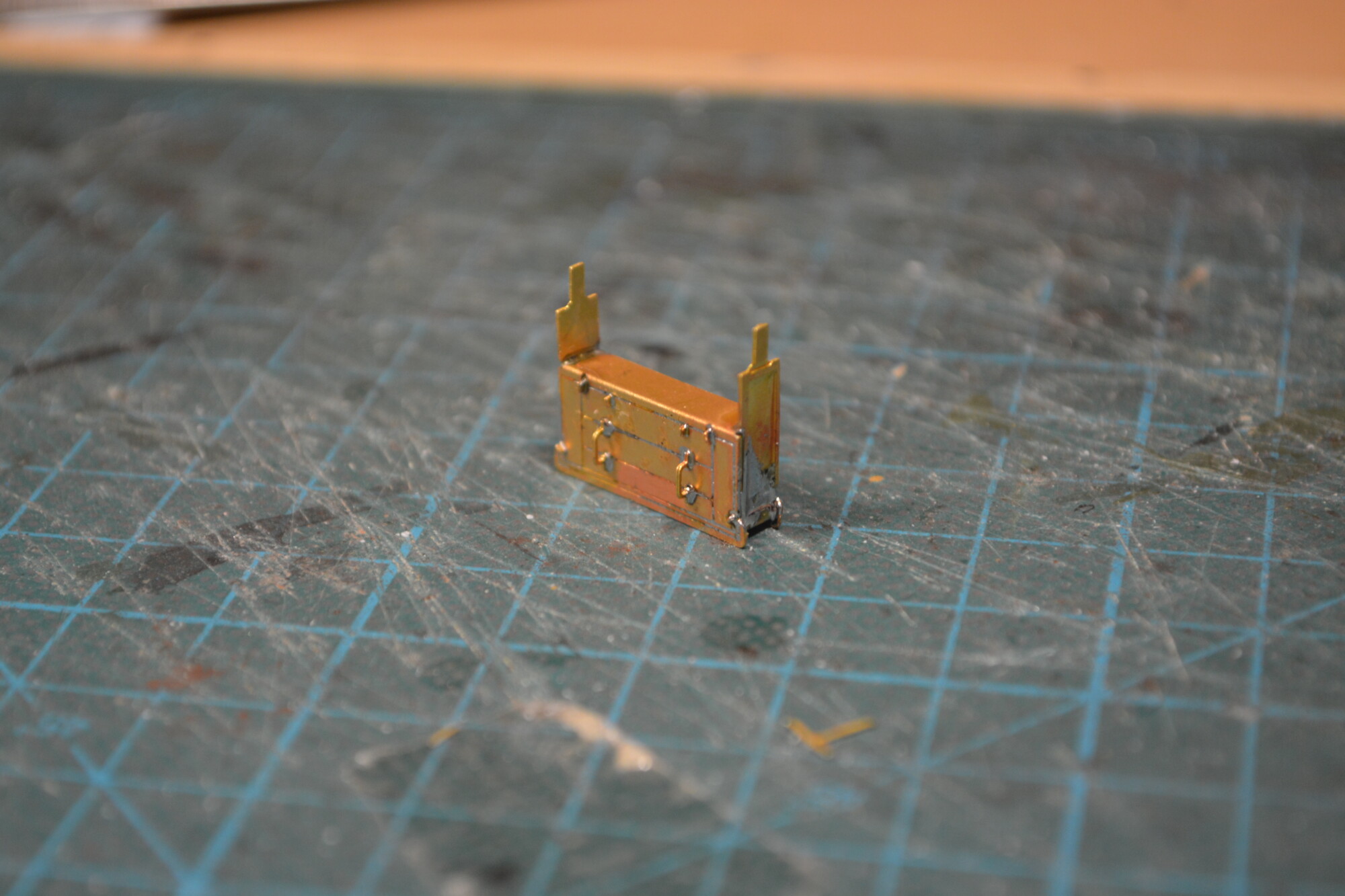
The next step was a little tricky – the little decorative edging strip that runs along the back side of the box. To fix this in place, I held the battery box in the vertical position with a helping hand, and push-fitted the strip onto the box. I could then carefully apply a lot of heat and a little solder, and the solder flowed nicely along the entire join, making it extremely strong. I think this is one of the joins where soldering is demonstrably better than glueing, as I suspect that the same joint glued would not stand the test of time.
The final step was to add the two handles. These were quite easy to fit, as they have lumps on their legs to stop them at a certain distance from the box. To fix these, I loose soldered one leg, then straightened the handle to be perpendicular by re-heating the joint and adjusting with tweezers, before soldering the other leg to complete the job.
Underframe detail
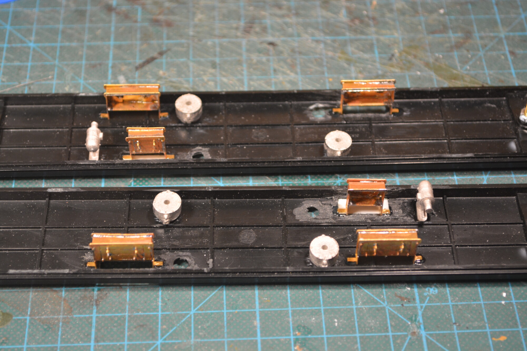
With the battery boxes complete, it was time to start populating the underframes with the various components that I’d gathered. To get an idea of where things should go, I used a combination of the SWaS video and the (relatively) newly-announced Rapido B-Set. The latter proved valuable as they’ve thoughtfully provided a scale 2D CAD drawing of the side elevation of the coaches. This allowed me to take measurements and work out where things belonged.
First to be fitted were the battery boxes, and then the vacuum cylinders and dynamo. I used Rocket CA glue to fix all these in place. I made sure to give the glue plenty of time to cure in the airing cupboard – the white metal items are fairly heavy for their size, so I wanted to make sure they were properly attached.
After attaching these items, I started to build up the underframe bracing, beginning with the vertical posts on the outer corners of the centre section, followed by the angle section that attaches to the verticals and provides the strength to the chassis. The verticals are 1.5mm square styrene lengths, and the angle is 1.5mm angle stryene, both from Evergreen.
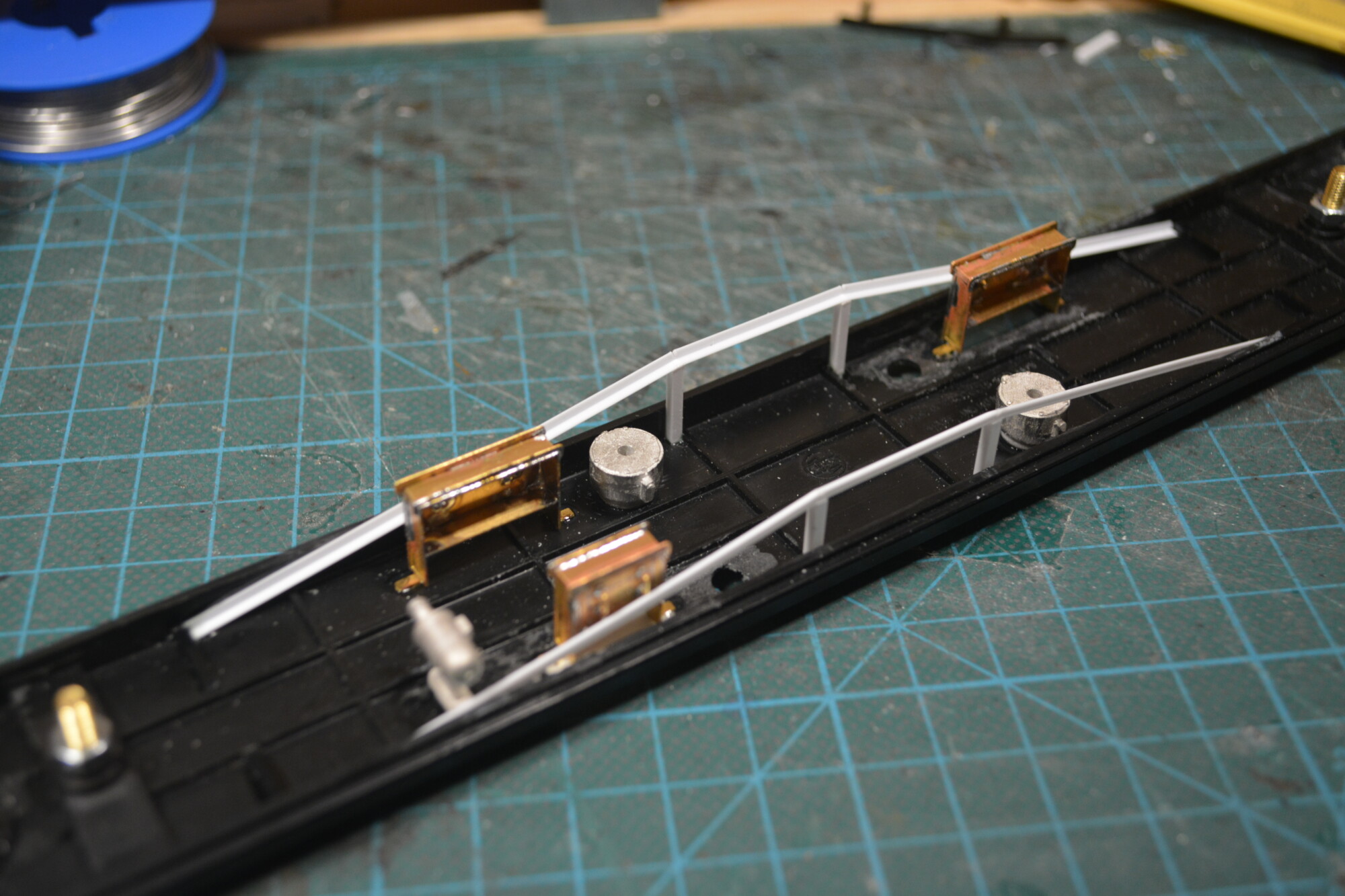
I installed two horizontal cross-pieces between the outer verticals and then added the final two assemblies. In the photo below I’ve also added the V-hangers from the Mainly Trains MT234 set.
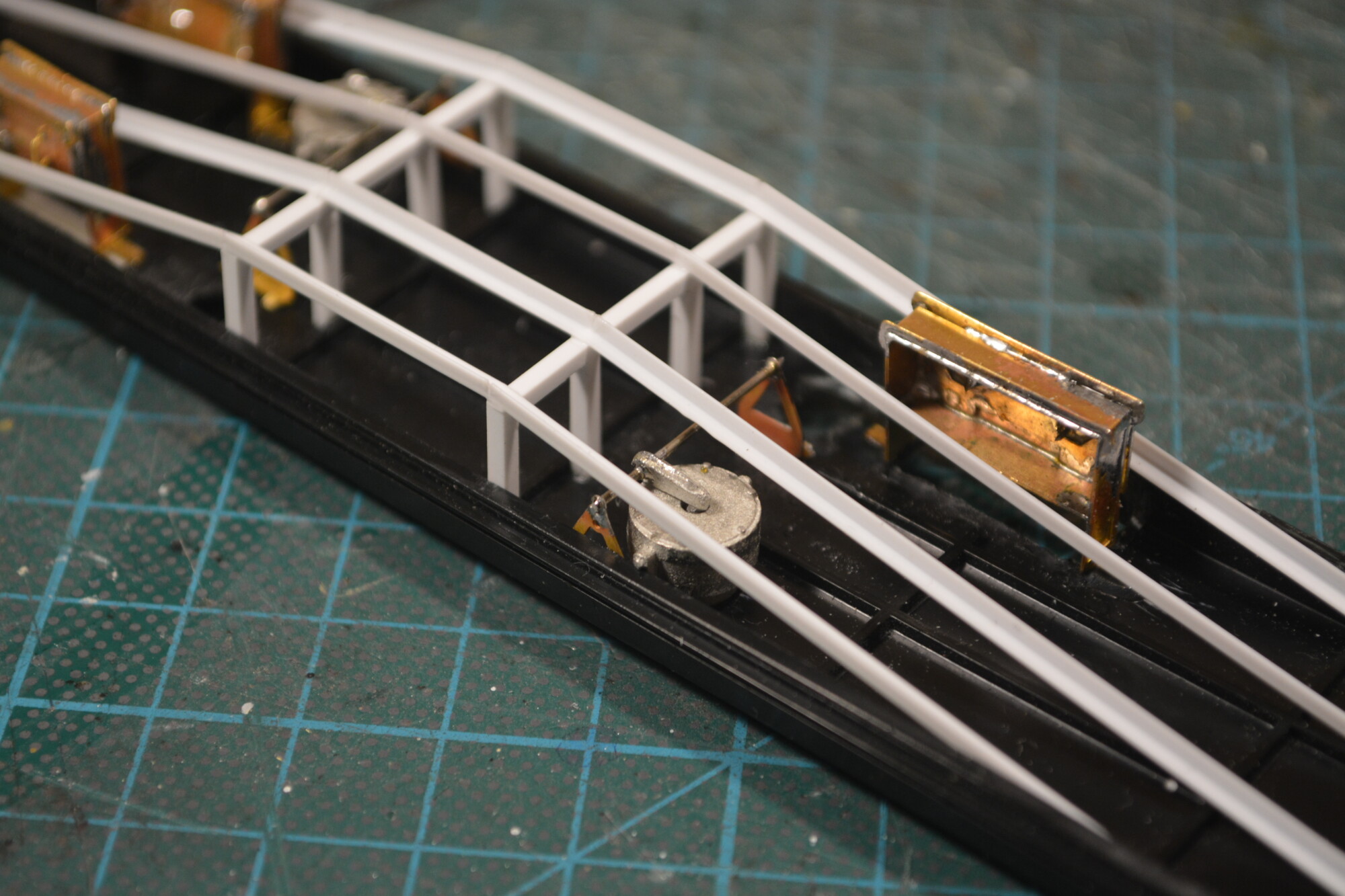
The last piece of underframe detail was a simple length of wire to represent the brake-rigging that between the vacuum cylinders and the bogies. This is a piece of 0.8mm piano wire that I cut to length and glued in place.
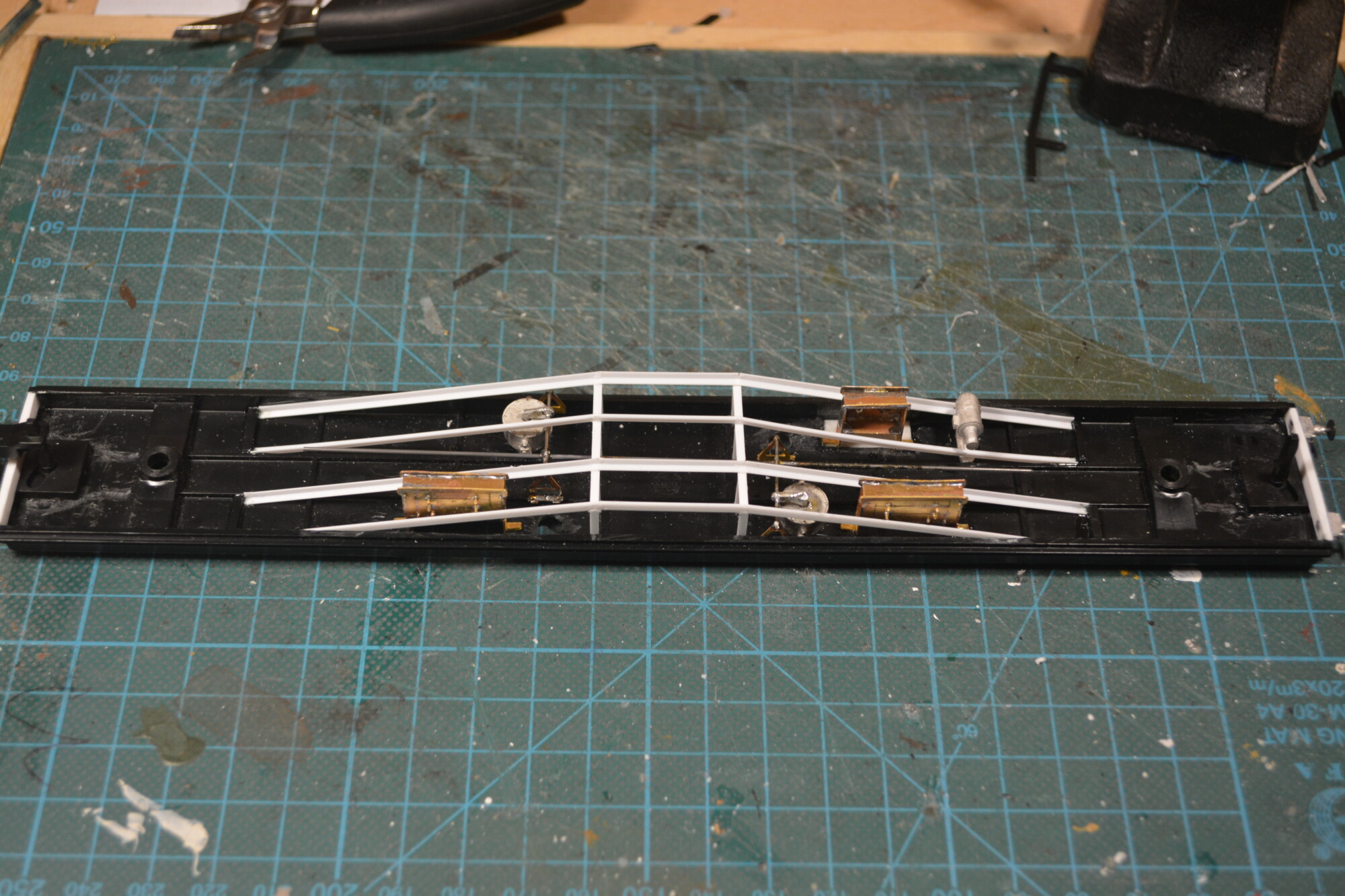
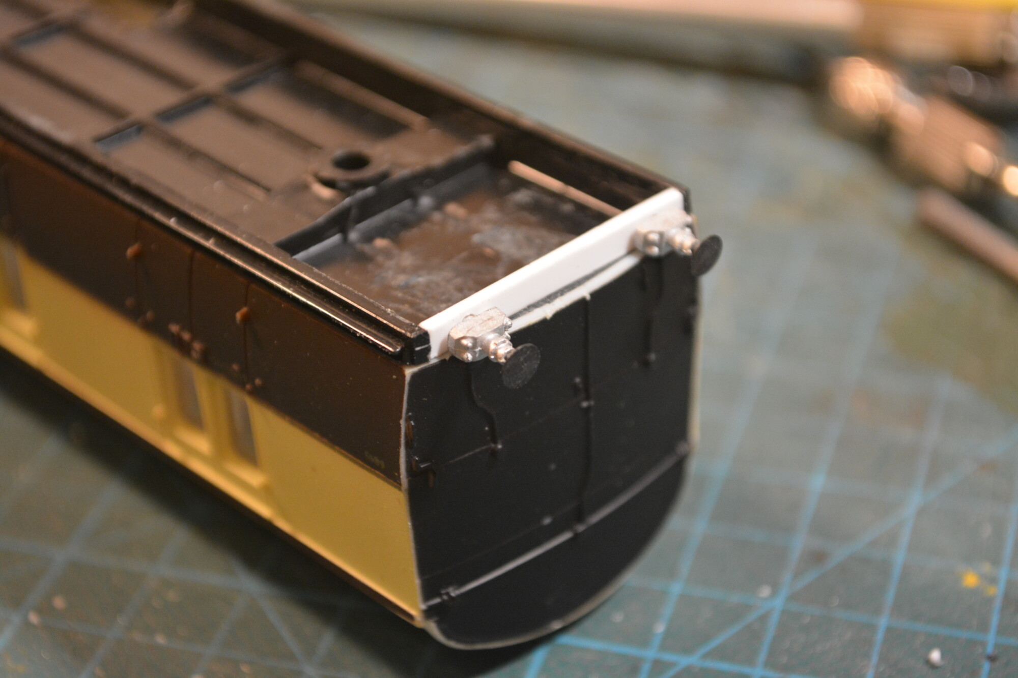
With the underframe components now installed, I also installed the Symoba close-coupling mechanisms, right up against the buffer beams. These were fixed in position with CA glue.
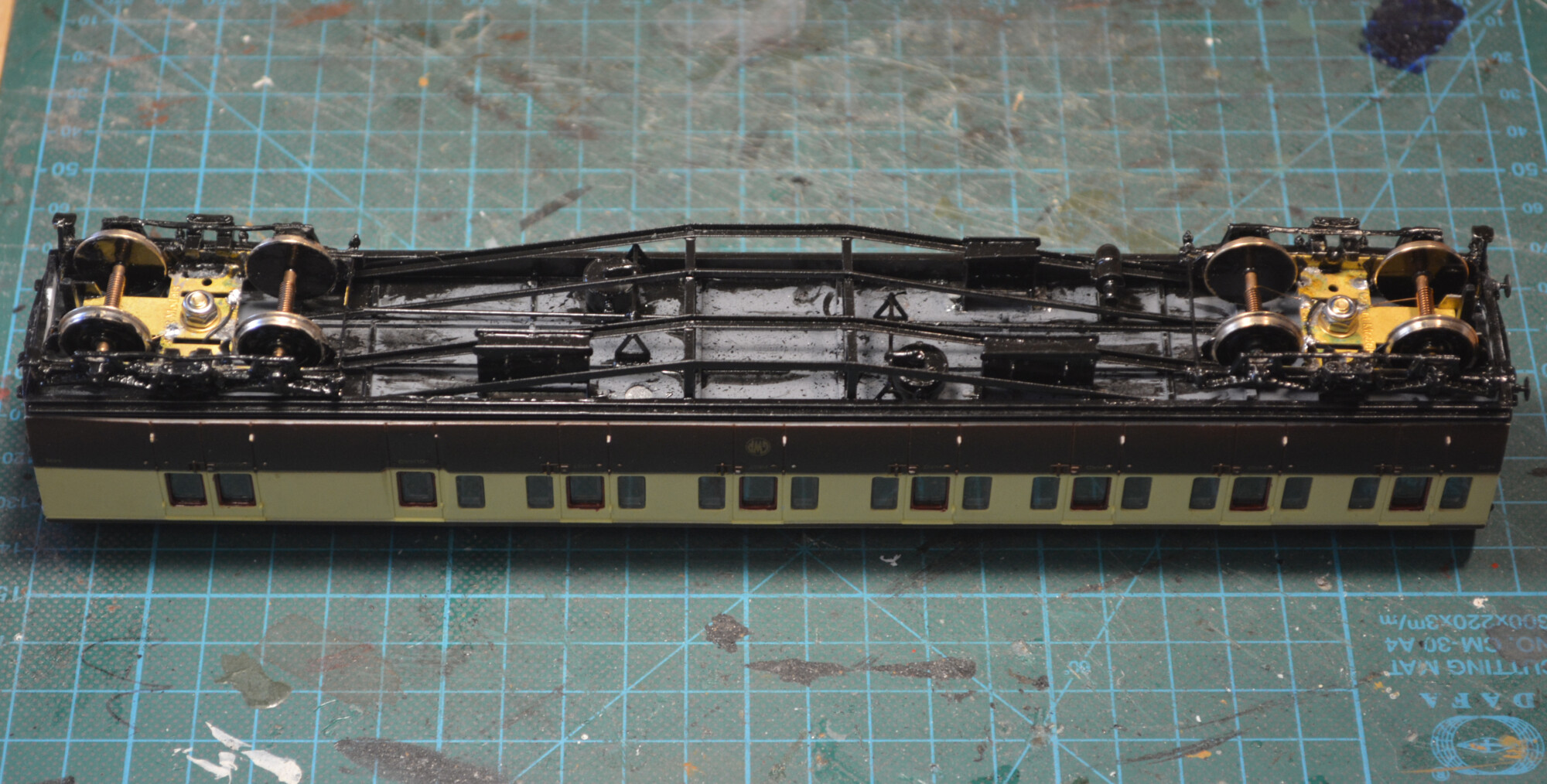
Painting
The underframe was primed using an all-purpose primer, and then given two watered-down coats of the the same black paint as I used on the bogies.
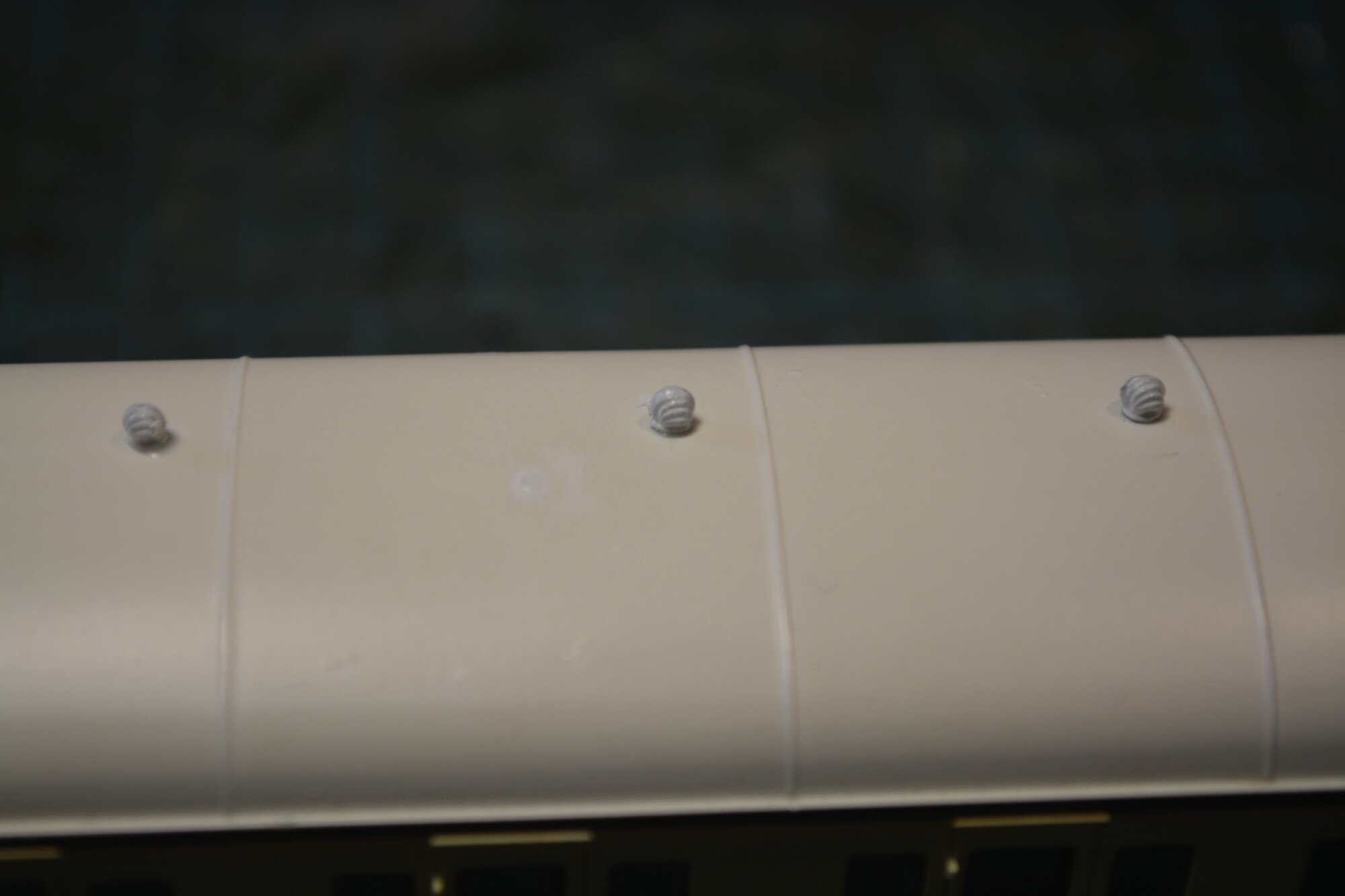
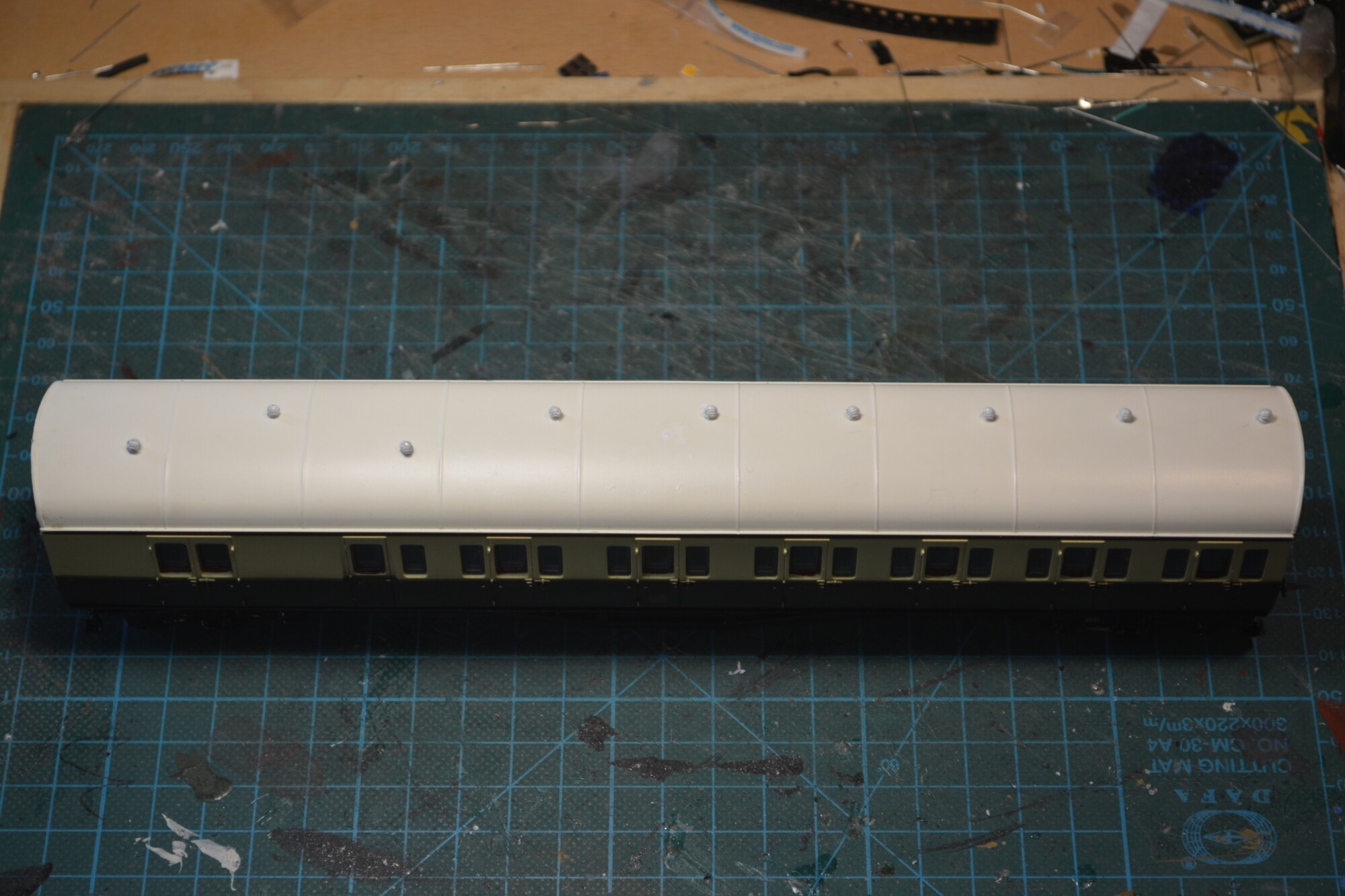
Roof
There wasn’t much wrong with the original roof vents (they’re rather nicely detailed), but I’ve lost a few over the years, so I replaced all of them with white metal ones from Comet. This was simply a matter of pulling each one out (or snapping it off if it was well glued in), drilling an appropriate-sized hole, and fixing the new vent in place with CA glue.
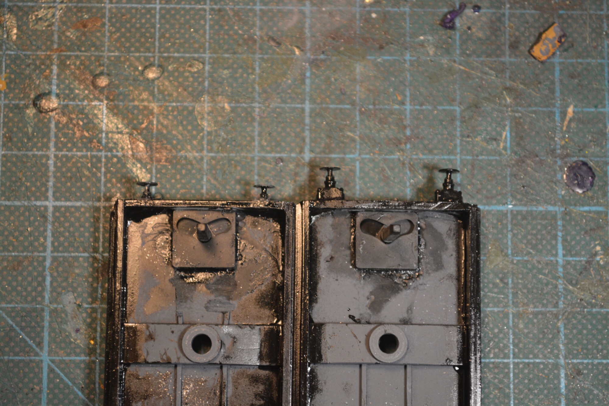
Tweaking the buffers
After comparing the coaches with the 2D-drawings from Rapido, I decided I was not happy with the buffers I’d fitted. They’re nicely detailed, but the inner buffers in their drawings are much shorter than the ones I’d fitted. So I removed them, cut the large rectangular bases off, and re-fitted them. The photo below shows the difference this made.
Interiors
The last major step was to upgrade the glazing and paint the interiors, so the coaches look better when lit (see part 2 for the lighting installation).
Glazing
I initially intended to use some Flushglaze windows, but when they arrived and I test-fitted one I found it looked noticeably worse than the original glazing. They did sit slightly “flusher” to the outside, but the major downside was that the edges where the glazing wraps around from the face to the sides were very rounded, leading to a “glass bottle top” effect that I wasn’t happy with. So I decided to stick with the original glazing panels, which would mean more painting…
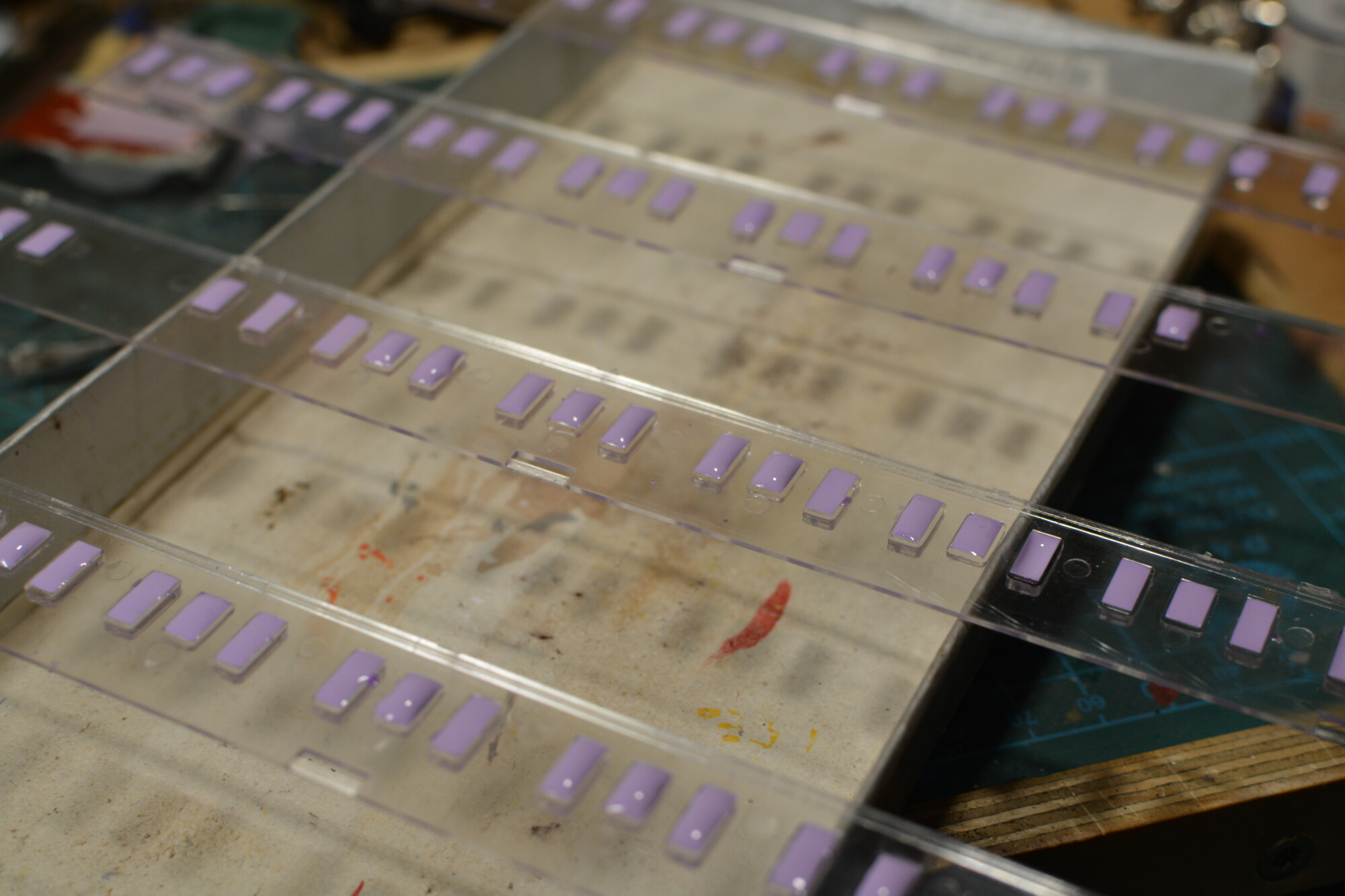
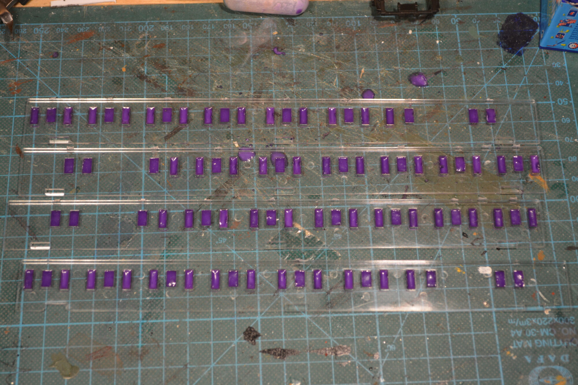
Painting
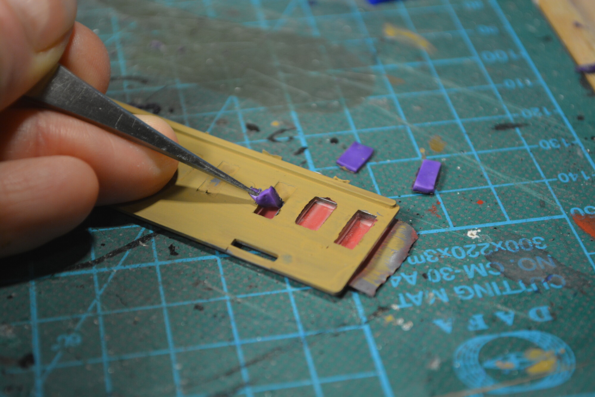
As with almost all coaches, the glazing is one solid panel, which means that when lit, the side walls in each compartment will be very obviously shiny. So I took advantage of each window being a recessed well in the panel by filling the wells with Humbrol Maskol. This is brilliant stuff, as you apply it wet with a brush or dropper, wait for it to dry, then do your painting, and finally peel the dried lumps or layers off.
One thing I learned the hard way is to make sure you apply a thick enough layer. I recently messed up some windows on my nice new Hornby MK3 Sliding Door coaches by not applying enough Maskol to the windows, and the primer I then sprayed on made its way through and attacked the plastic in places.
Once dry, the sides could then be primed and given a couple of coats of a plain “woody” colour. I wasn’t too fussed what colour this was, as it won’t be that visible through the small windows.
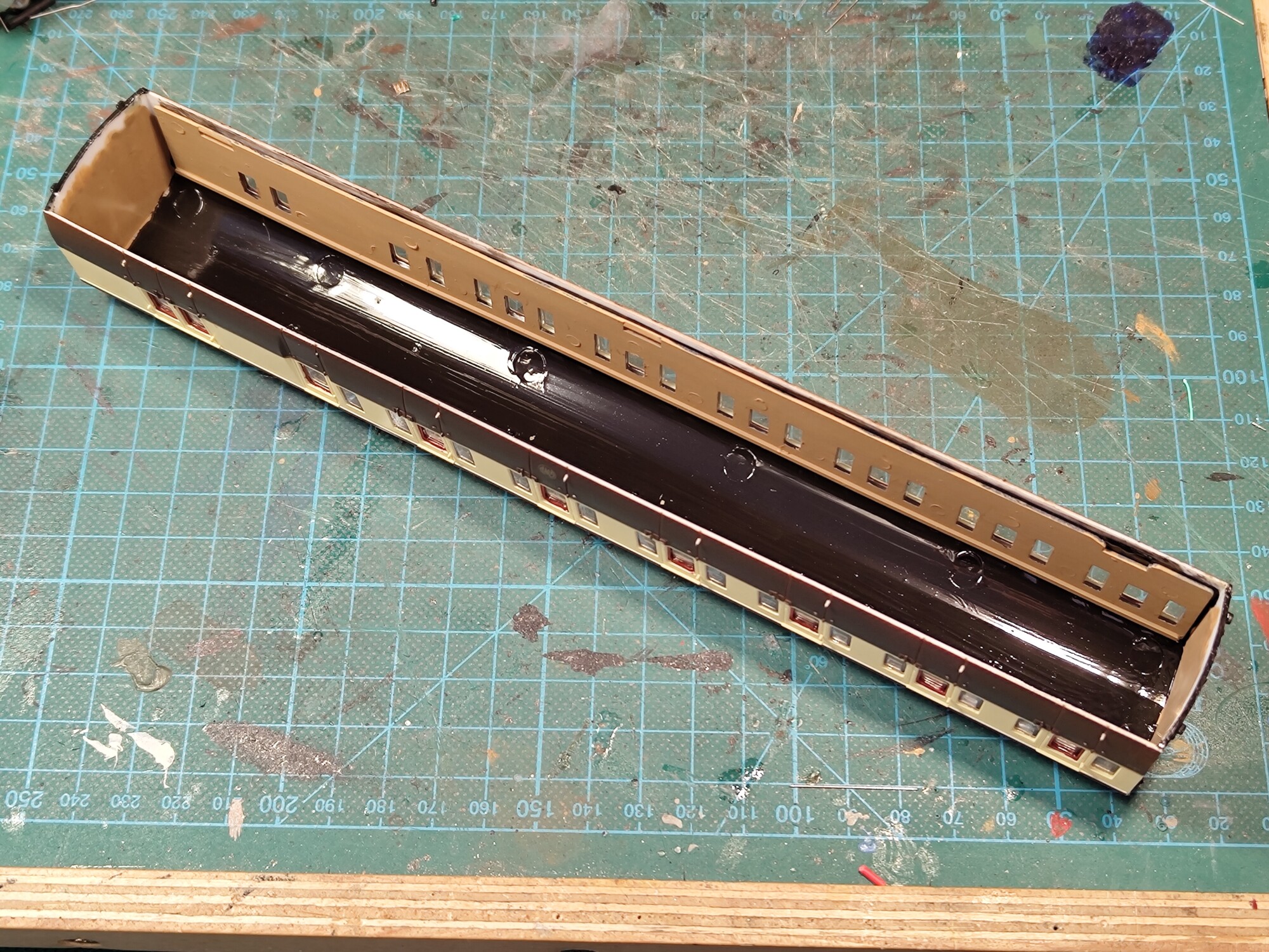
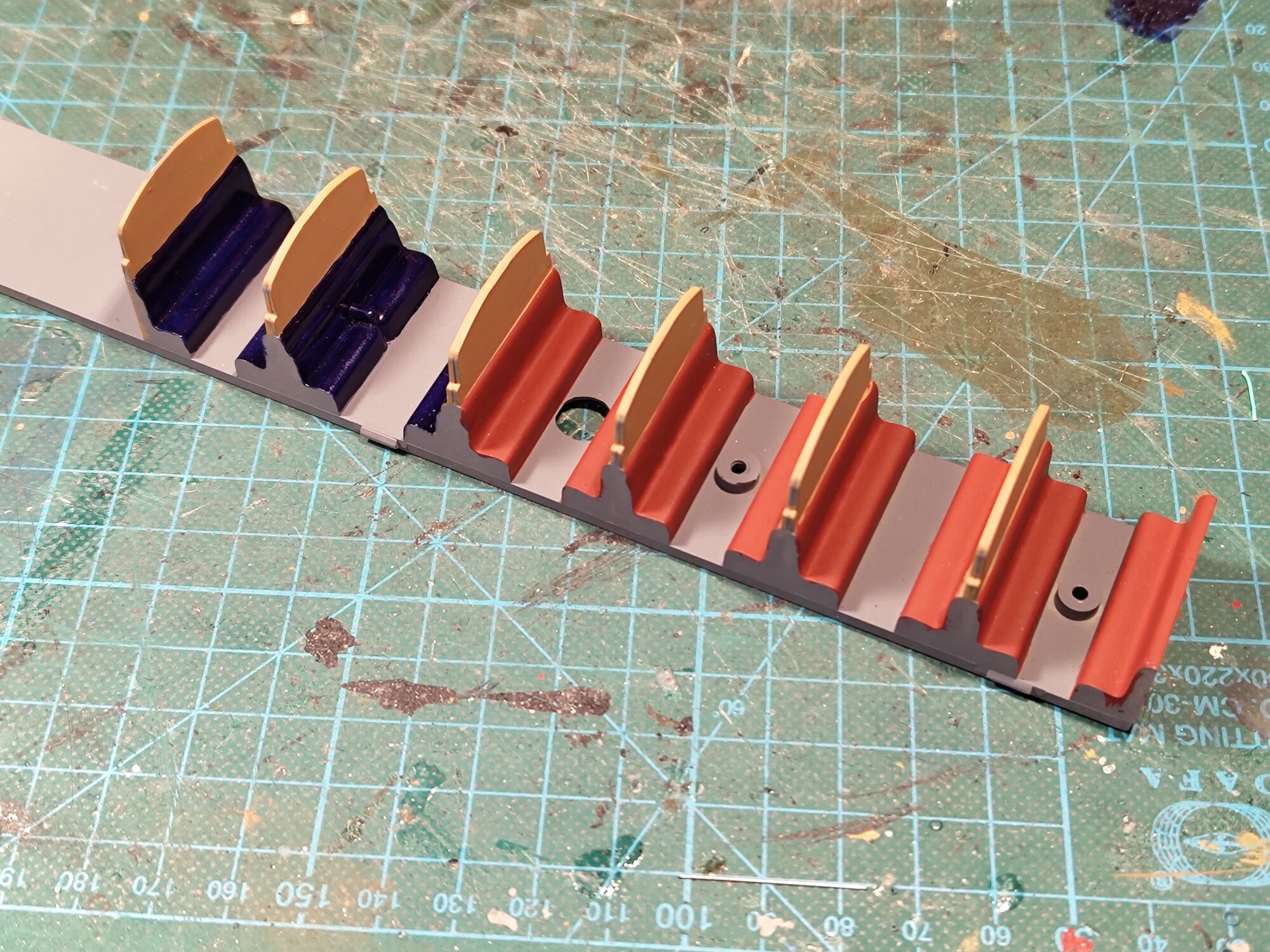
Seating
The seating pieces were given a coat or grey primer, which also serves as the floor colour, and then the seats were painted either red for third class, or blue for first. Here I noticed a quirk of the original model. The seating pieces have one first class compartment (larger and arm-rests between seats) and five third class compartment (smaller and no arm-rests). However, on the body, there are four first class and two third class compartments – the one before the guard’s compartment has “first” written on the door.
Using Rapido’s drawings, I concluded that the seating piece is correct, and the printing on the body is wrong – I suppose some wires must have gotten crossed at Airfix back in the 1970s! However, I decided to decorate the final compartment as if it were first class, as I don’t plan on changing the transfers on the body. This isn’t strictly correct, but it doesnt bother me that much.
Window droplights
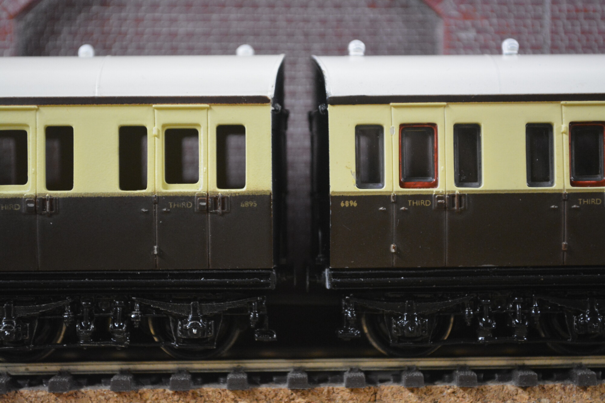
I followed both the Rapido drawings and the SWaS video and painted the droplight inserts in the compartment doors a reddish-brown to give a mahogany effect. The paint I ended up using for this was EWS maroon, and I think it came out rather well.
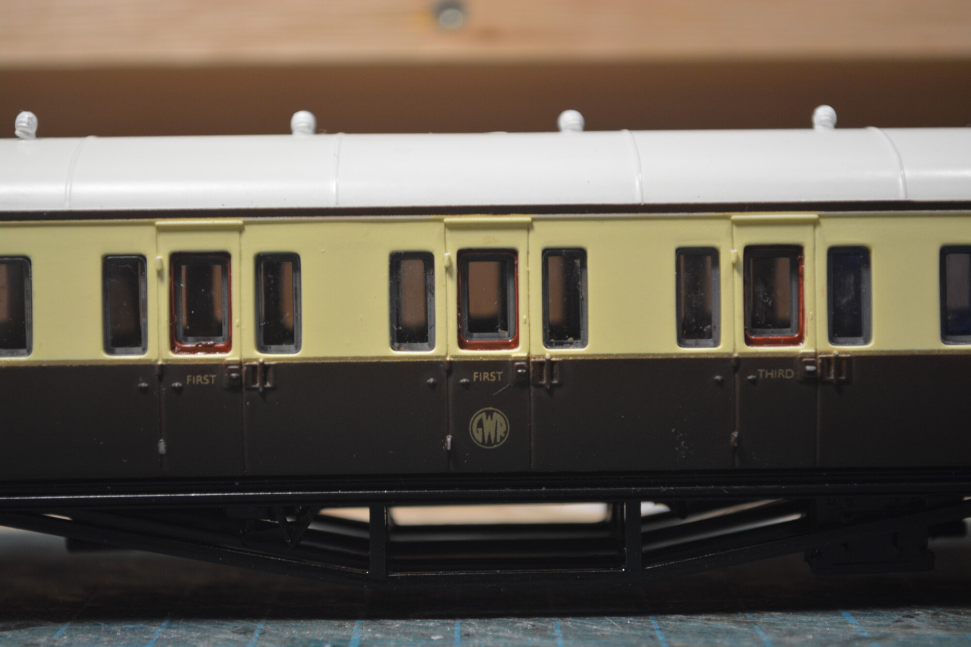
Painting these inserts has had a big impact on the look of the model in my opinion. In fact I’d say that if you didn’t want to spend that much time on your B-set (but still wanted to do something) this one-hour job gives the most “bang for the buck” by far.
The end result
This project has been a lot of fun. In part this is due to the fact I’ve had these models for over 20 years, and it’s really satisfying to see them get a new lease of life, instead of simply replacing them with newer models and forgetting about them.
The other reason I’ve enjoyed it is that it’s arguably the first “proper modelling” (i.e. removing old components, adding new kit-built ones and even scratch-building some elements) I’ve done on a piece of rolling stock, and I think the result was reasonable.
Yes, the models still aren’t perfect, and yes some of the paintwork and transfers aren’t up to modern standards, but it’s my B-set, and now it looks quite a bit more respectable running on my layout.
Next time…
The next step for these coaches is to add lighting to them. When this is done, I’ll add a link to part 2 here.