
I have had a Hattons class 66 in Freightliner livery (66957 – Stephenson Locomotive Society) on order since they were announced back in 2018. With the delivery date fast approaching, I’ve ordered a mixture of container wagons in Freightliner livery for it to haul when it arrives.
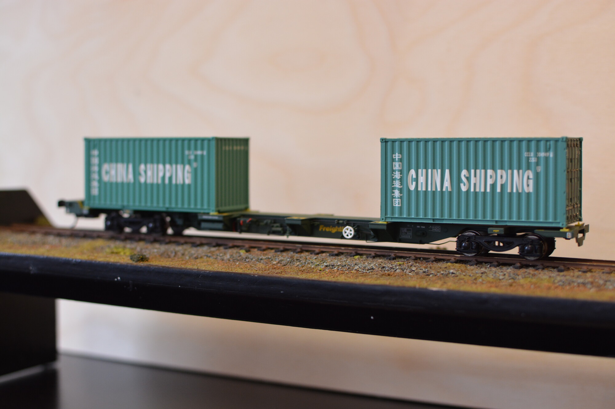
The first of these wagons to arrive are three pairs of Dapol’s excellent FEA-B spine wagons. These wagons run in fixed pairs, typically in long rakes of mixed intermodal wagons. I used to see them every morning during my commute between Reading and Chippenham (a lot of container traffic passes through Didcot, mostly to and from Southampton docks I believe).
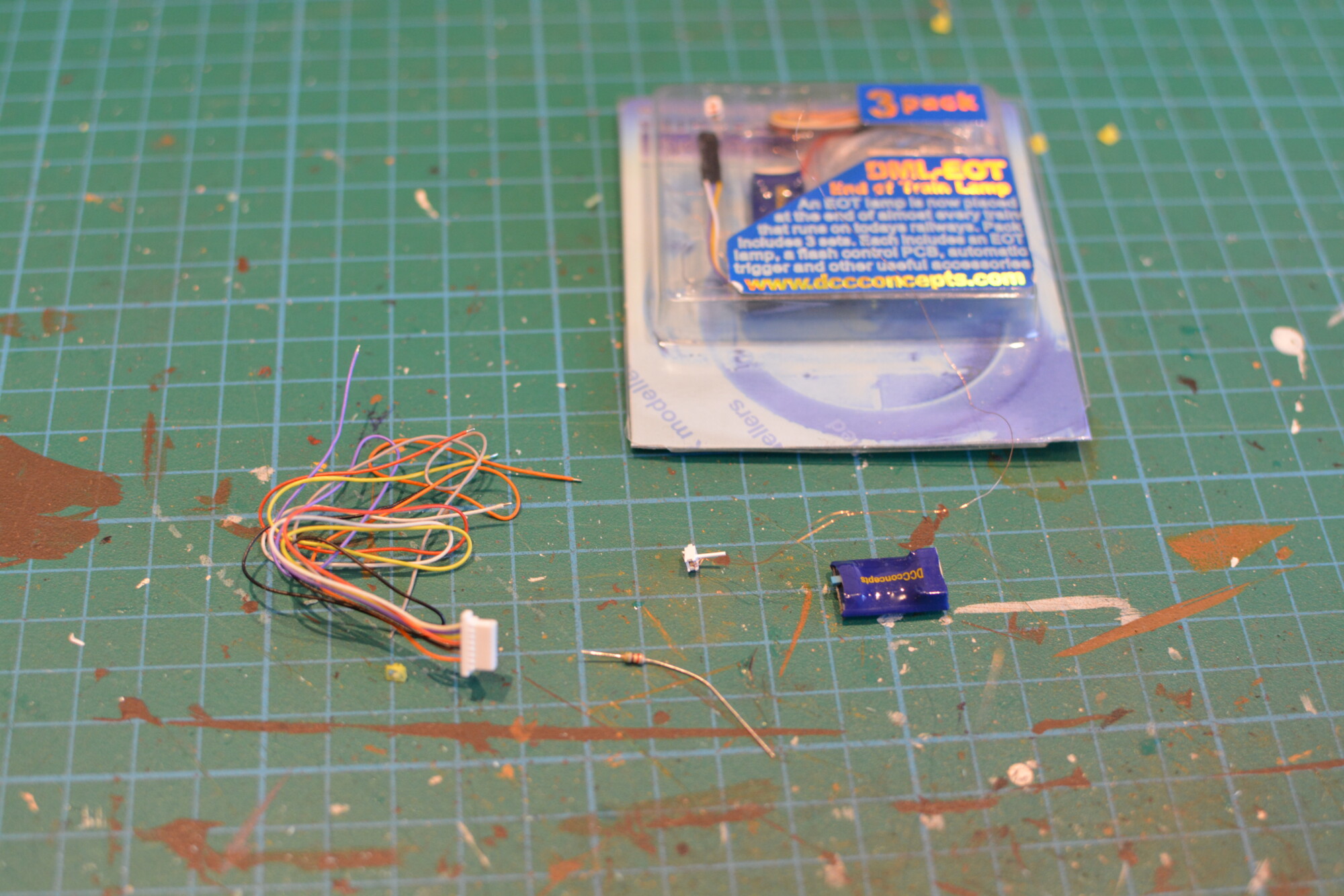
All freight trains on the network today must carry an End-Of-Train lamp on the rearmost vehicle. These are portable battery-powered lamps with an array of red LEDs that flash every one second or so. DCC Concepts happen to make a working scale model of these lamps, and I was keen to see how they look on the back of a wagon, so I bought a pack of three.
The tricky part of this job will be finding a place for all the electronics – I need to find a space to hide not only the control unit and its harness, but also a DCC decoder and keep-alive capacitor (since I want to be able to switch the lamp on and off at any time). With a hopper or box van, all of this equipment could be hidden inside, but these spine wagons are by their very nature totally open. I’ve therefore decided to hide everything inside a semi-permanent container at the rear of the wagon. This does mean that I can never run this particular wagon fully empty (as these wagons are often seen on whilst in operation), but there really is no other choice.
Block diagram

Power will be picked up from the rearmost bogie on the wagon and fed to the DCC decoder. The F0 (forward head-light / tail-light) output from the decoder is then fed to the EOT control unit, which takes care of strobing the lamp once per second. The output from the EOT is run through a 5K resistor to limit the current passing through the LED to a suitable level.
Since the container will be removable, the DCC signal input and the supply to the EOT lamp will be connected via pin headers and sockets. This will allow the container to be fitted to the wagon easily.
The DCC decoder I’ll be using is the humble Hornby R8249 basic DCC decoder. I have several of these lying around not being used. These decoders are not great for driving locomotives as they lack quite a few rather useful features, and the motor drive is also not particularly good. As shown in the diagram, an energy storage module (or keep-alive) will be fitted. This will keep the decoder powered for a few seconds if power is lost, thus ensuring the lights stay on, even on dirty track. This energy storage module consists of a large capacitor with a resistor to limit inrush current (so that the decoder will not draw a large current when placed on the rails – this could cause a DCC district cutout or command station to trip out). The diode in series with the resistor is there to allow current to flow from the capacitor to the decoder unimpeded as required.
Bogie pickups
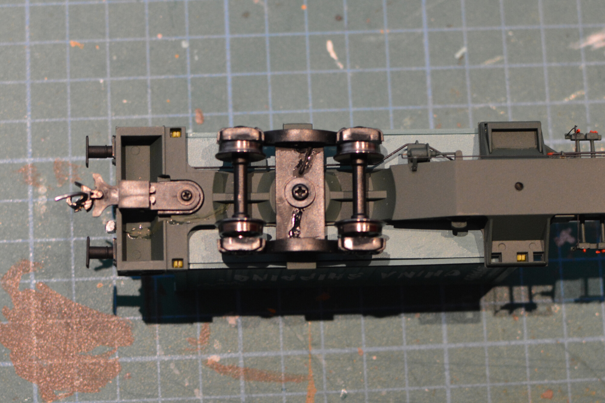
The first step is to add pickups to the rearmost bogie on the wagon. Fortunately, these wagons use split wheelsets, with a plastic centre axle and two wheels live to metal pinpoint ends. This means that we can easily pickup current from the wheels by adding brass pinpoint bearings, and soldering wires to these bearings. The beauty of this solution is that it will add absolutely zero extra friction to the wagon. Friction can be a major problem when using wiper pickups or axle springs to pickup current, especially when running long passenger trains (for example a 10-coach train might be picking up current from 40 axles).
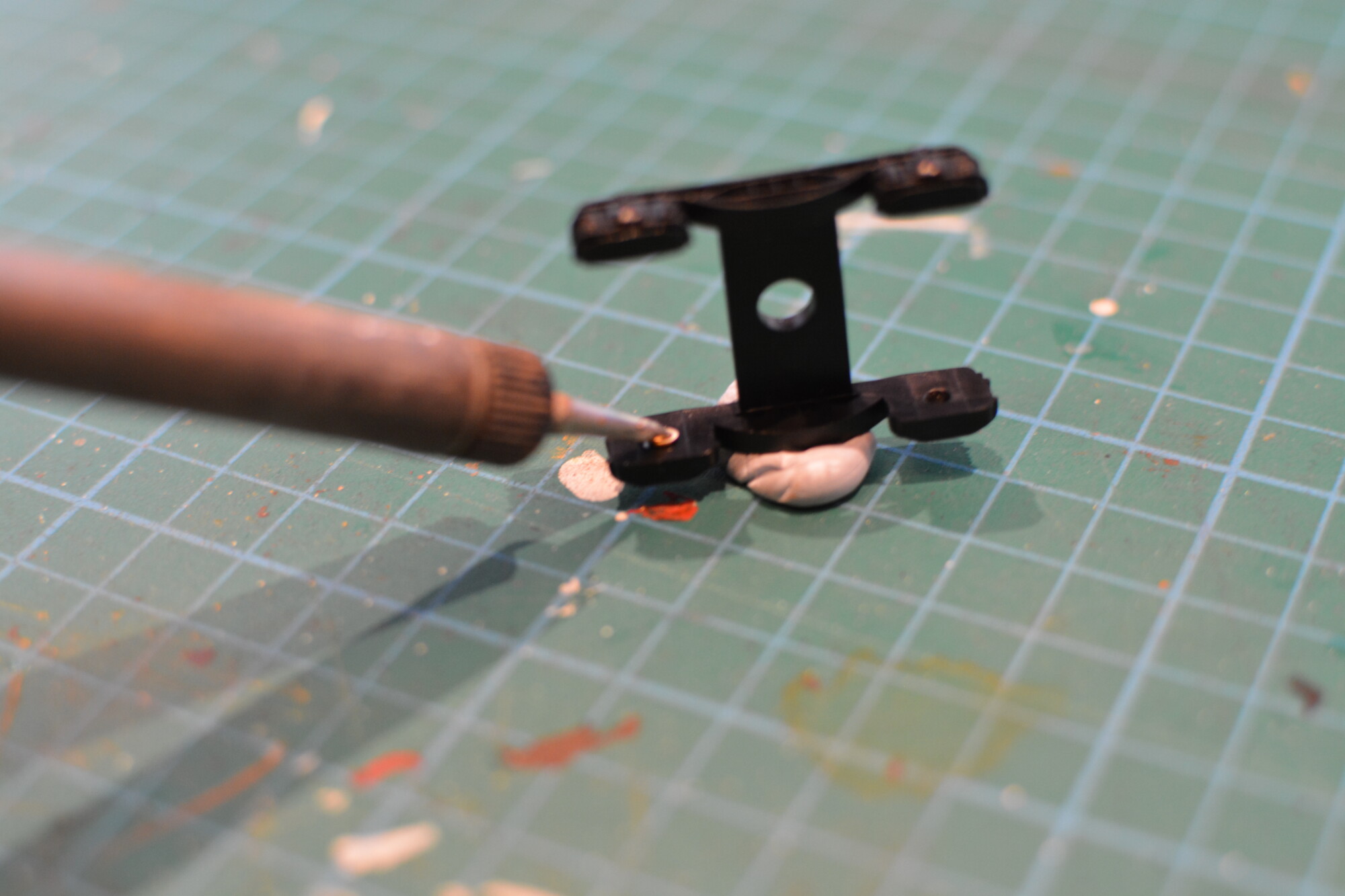


Now it’s time to re-fit the wheels. Because the bearings are mounted flush with the inside edge of the bogie frame, the point-to point axle length must be reduced by about 1mm. This was done by turning each point down in small steps, testing after each time, until the wheels spin freely and there is no side to side slop in the axles.
Attaching the lamp


Initial testing
Before installing all the equipment in the container I ran a quick test to test that the decoder and EOT control unit work OK. In the photo below you can see the lamp “mid flash”, so everything appears to be working!

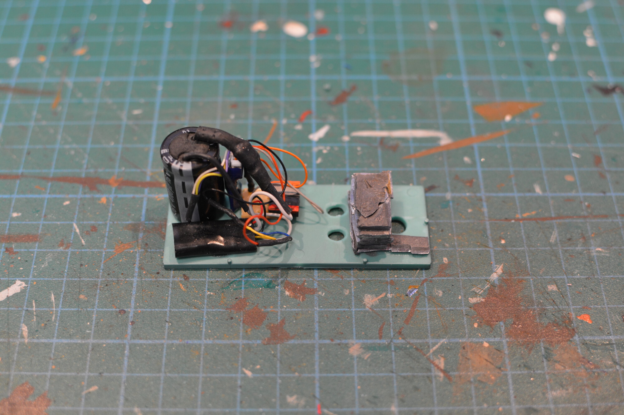
Installing the container
Now it’s time to fit all the equipment to the base of the container. The energy storage module was glued down first, followed by the four-way header, then the Hornby decoder and finally the EOT control unit. I also added some lead to weigh the wagon down and thus help with electrical pickup.
The finished wagon
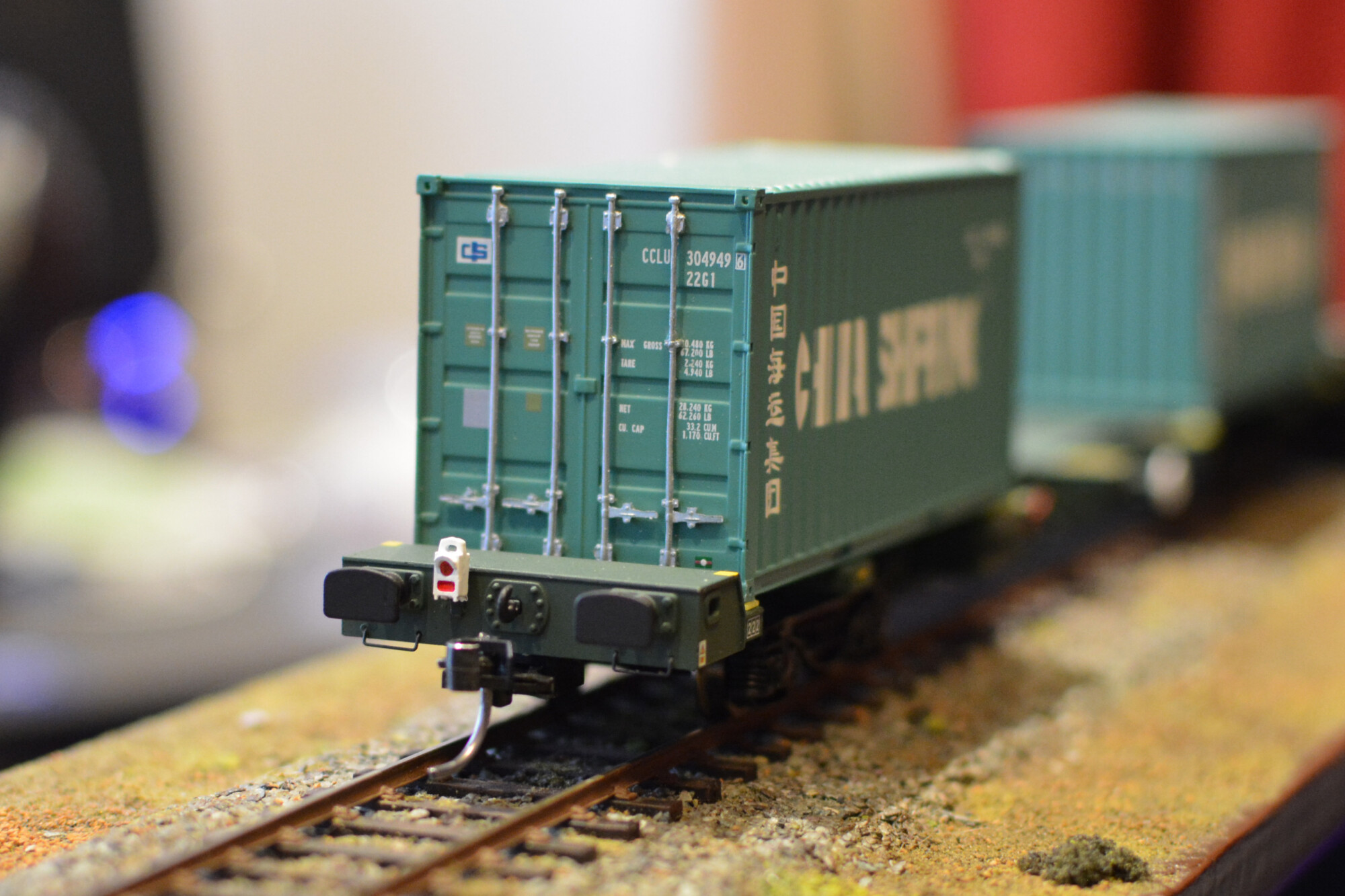
I’m really happy how this project turned out. It took about 8 hours start to finish (including planning), but was well worth the effort in the end. The pickups from the bearings work beautifully, and the keep-alive capacitor pretty much gaurantees that the decoder will never lose power. I now can’t wait until my new 66 arrives in the post later this month!