
I have fitted DCC sound to a handful of locomotives in my collection, but so far, it’s only been diesels that have received the upgrade. Today that changes, as I’m going to be adding sound to one of my favourite (and most dependable) steam locos: My Bachmann 4MT 2-6-0 mogul.
After a bit of research online, reading various discussions and watching sound demos on Youtube, I decided to go with YouChoos for this project. I’ve never used them before, but their demo video for showing a similar 2-6-0 mogul seemed to be pretty good, plus they use Zimo decoders, which I’m very familiar with, so I took the plunge.
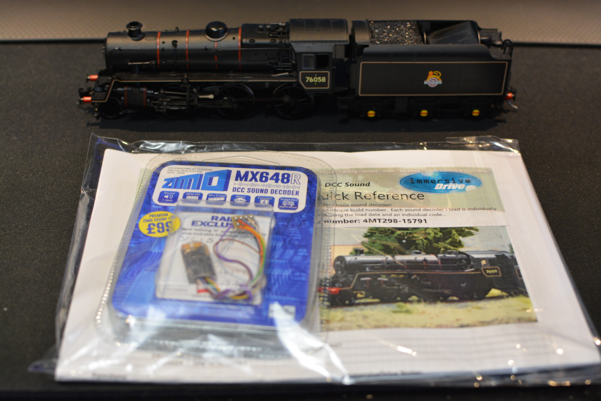
Based on the DCC fitting guide on the YouChoos site, I’m going with a Zimo MX648, which is essentially a smaller version of the MX645, with lower speaker and function power output ratings and no fly leads or circuitry for a keep-alive (more on this below). I’ll be pairing this with one of YouChoos’ own “sugar-cube” speakers (the SugarCurve 7), housed inside a 3D-printed enclosure. This particular speaker has a curved top that makes it suitable for fitting inside 4mm steam loco boilers.
Adding a keep-alive
Although the MX648 series of decoders provide neither drive circuitry for energy storage capacitors nor the circuitry required to properly use them, it is possible to fit a keep-alive to this decoder. In fact, it is possible to fit one to any decoder. In my recent post on adding a flashing lamp to some modern-image container wagons, I fitted a keep-alive to a bog-standard Hornby R8429 for example. The only extra work you need to do in this case is to add a diode and a 200Ω resistor (connected in parallel) to the positive leg of the capacitor, with the positive leg of the diode furthest away from the capacitor. This arrangement means that when current is flowing into the capacitor (i.e. it is charging up), the rate at which it flows (the inrush) is kept nice and low, thus preventing the decoder from potentially tripping out the DCC booster or district cutout. However, when current needs to flow out of the capacitor (i.e. when the decoder has lost power from the track for any reason), the diode allows the current to pass unimpeded. This is important as limiting the current with the resistor would mean the decoder would not get enough power to drive the motor, which would make the keep-alive fairly useless!
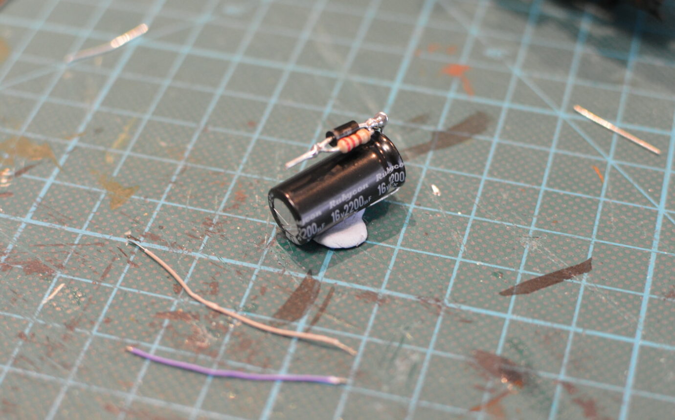
This particular model has space for a 2200μF capacitor in a hollow above the weight in the smokebox – this will give about 1 second of running after losing power, which is plenty (really anything above half a second is probably enough to get a loco over dirty track).
When adding a keep-alive to a decoder that does not provide leads or dedicated solder points for a keep-alive, the trick is simple: Attach the positive lead of the capacitor (in this case the positive lead of the diode-resistor pair) to the common positive (the blue function wire), and the negative lead of the capacitor to ground on the decoder. If it is not clear where this is, you can use a multimeter set to DC voltage to probe the PCB – place the positive probe on the common positive, and move the negative probe around until you see a reading of about 1.4V less than your DCC track voltage (typically 13-15VDC).
The installation
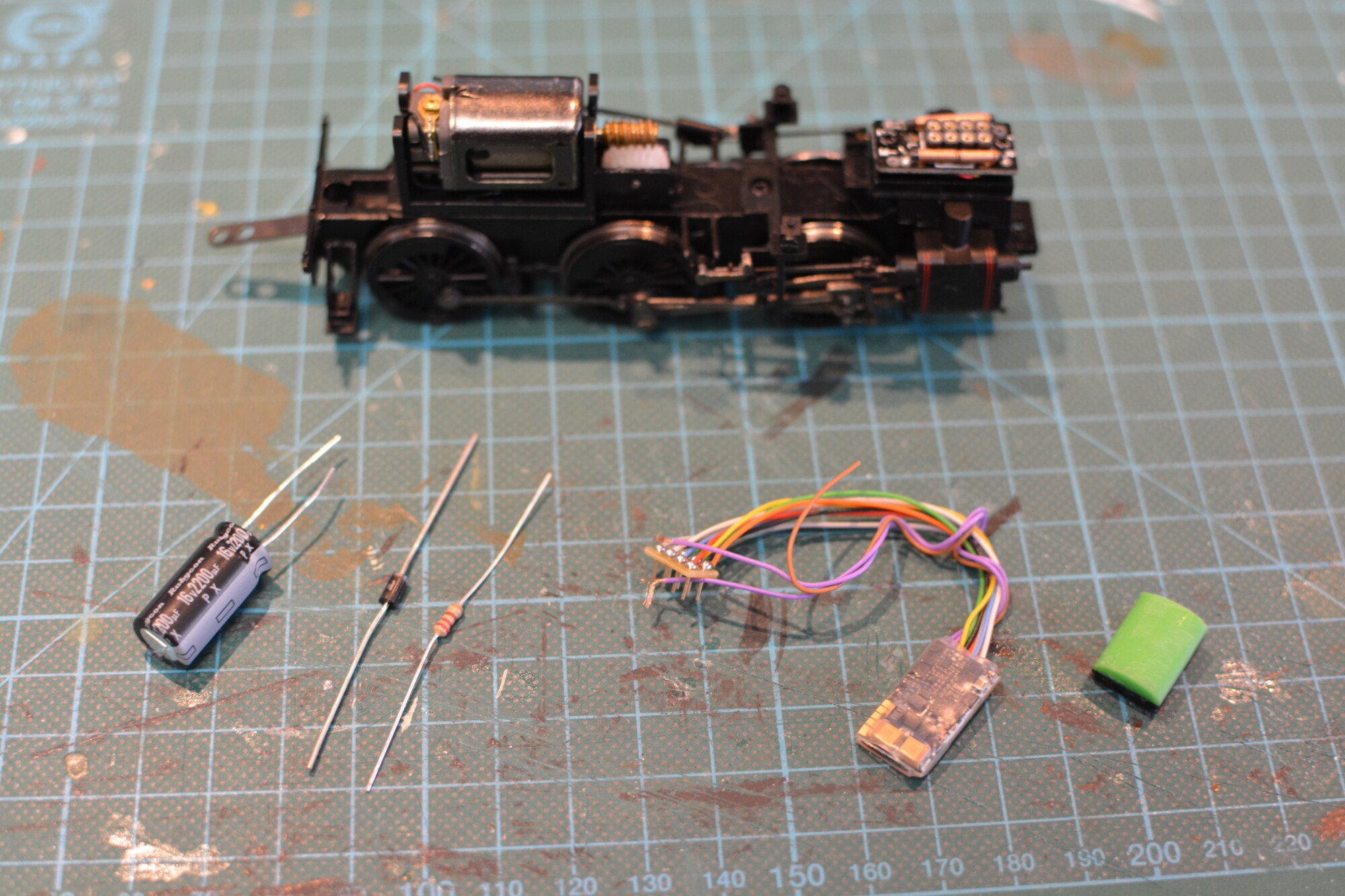
The first step is to remove the 8-pin socket from the loco. We are short on space in the smokebox area (I’m trying to cram a relatively large keep-alive, a decoder and a speaker into quite a small space) , so to get everything to fit it needs to go. The decoder will therefore have to be hard-wired, which isnt ideal, but there’s not much we can do about it.
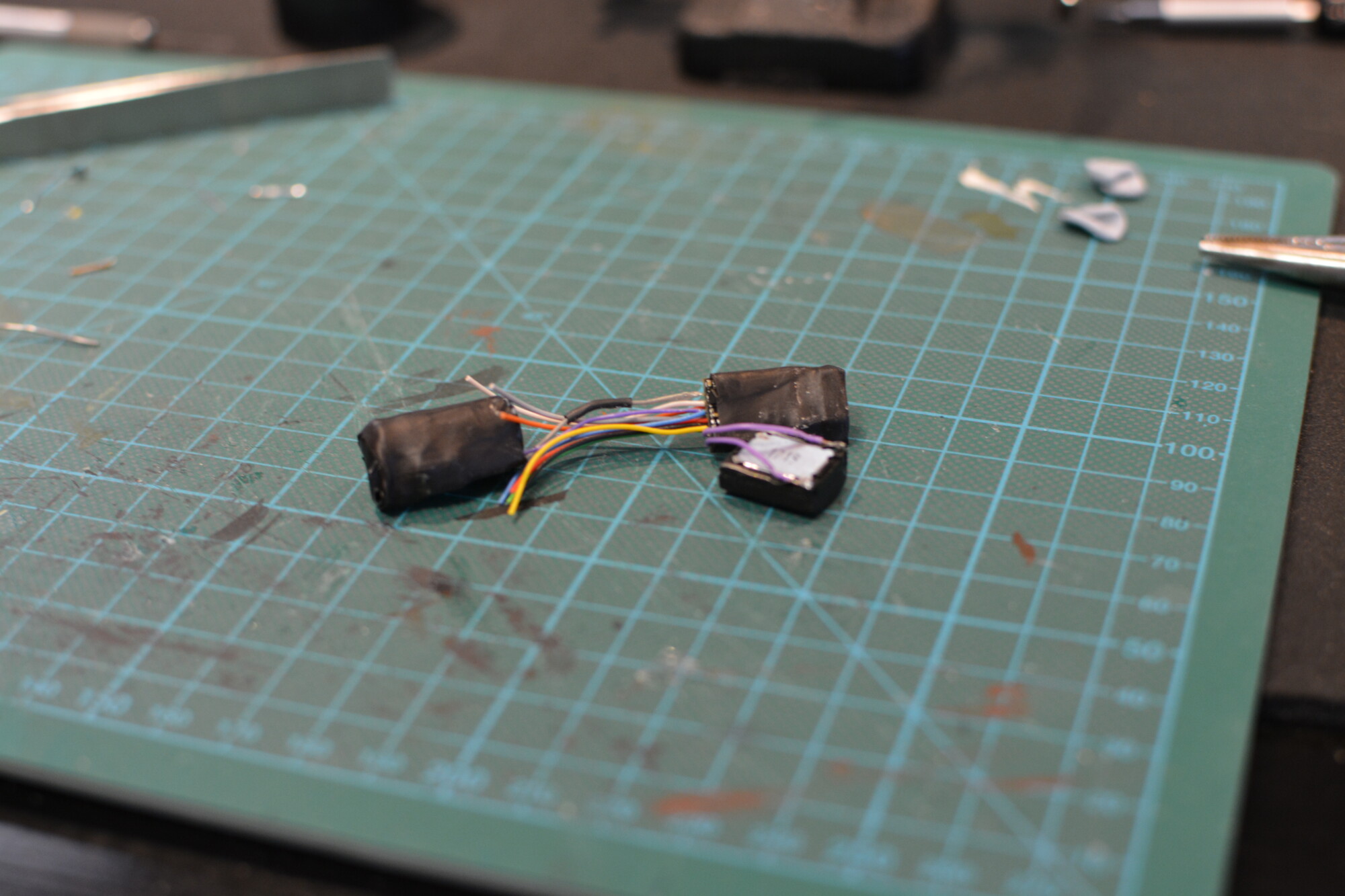
Next, I constructed the energy storage unit, making sure to make it as small as possible so it would fit inside the space above the weight in the smokebox.
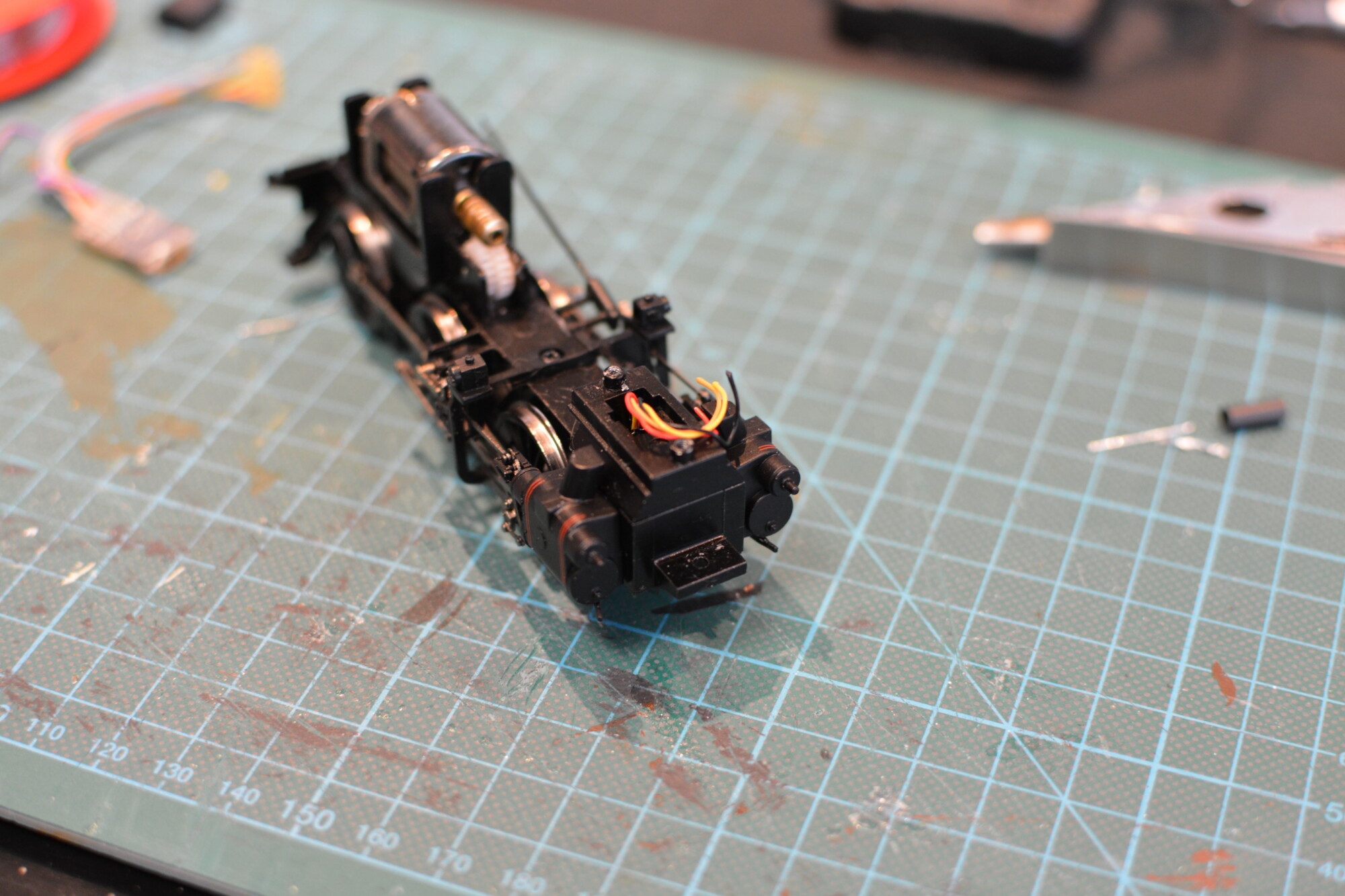
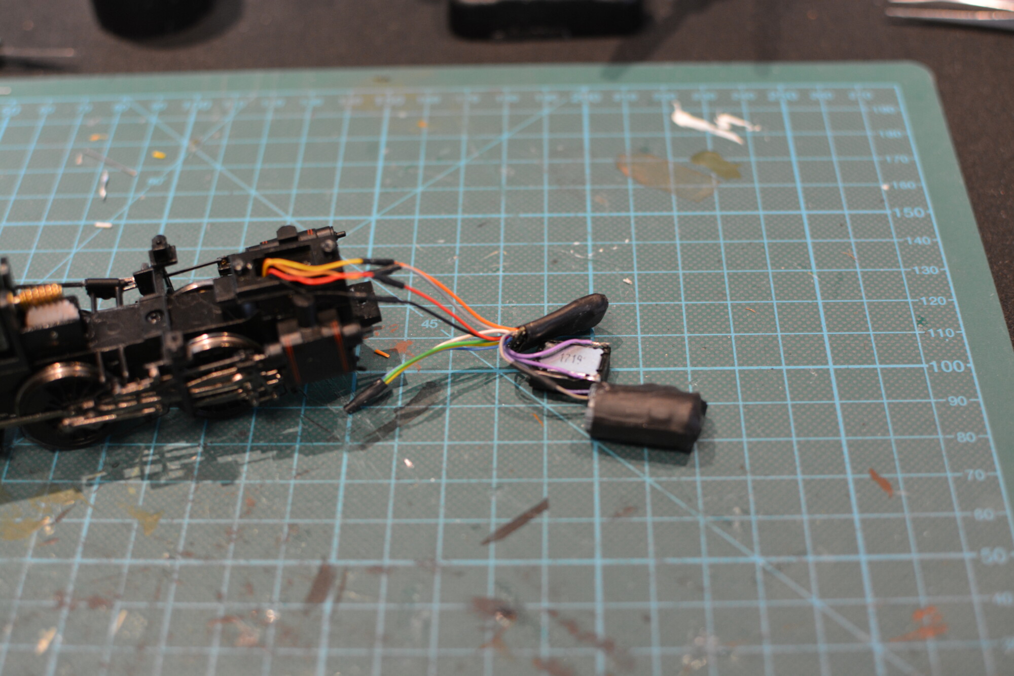
Now it’s time to connect the three components together. The speaker is wired to the two purple wires coming from the decoder, and can be wired any way round.
The last thing to do is to wire the decoder to the chassis. There are four wires to connect: Left and right rail, and motor positive and negative. I made sure to leave just enough slack on the wires to allow me to remove the body from the chassis, but not so much that it would make fitting the body tricky.
The finished article
Before re-fitting the body, the energy storage unit was slotted into the space above the weight in the smokebox, and the curved speaker was fitted into the smokebox (curved side up to match the curved body profile) and fixed in place with a couple of blobs of black tack.
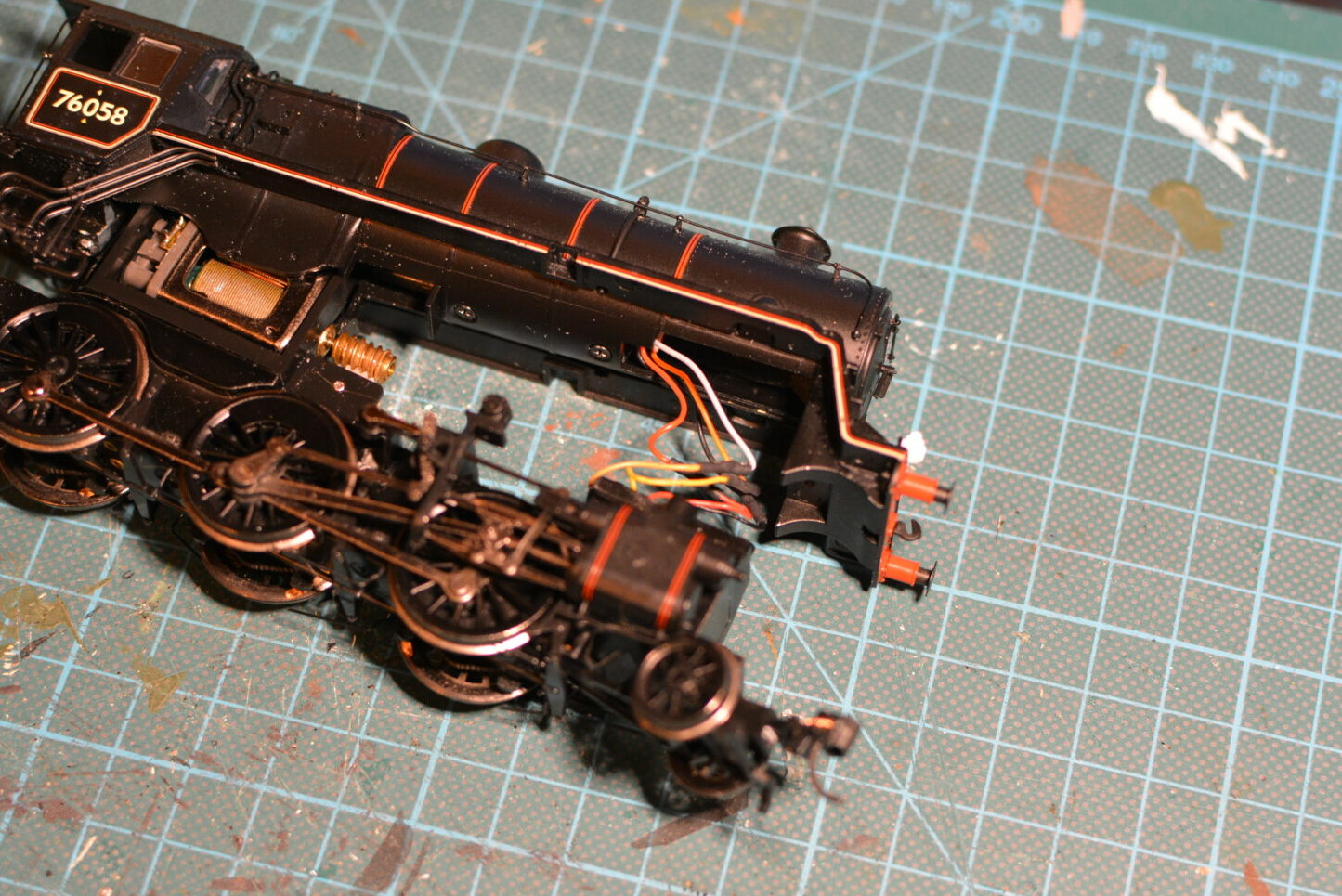
After that, the decoder was stuffed inside the body and the body re-attached. I didn’t have any problems getting the body down, so it looks like measuring the space inside the smokebox dozens of times paid off!
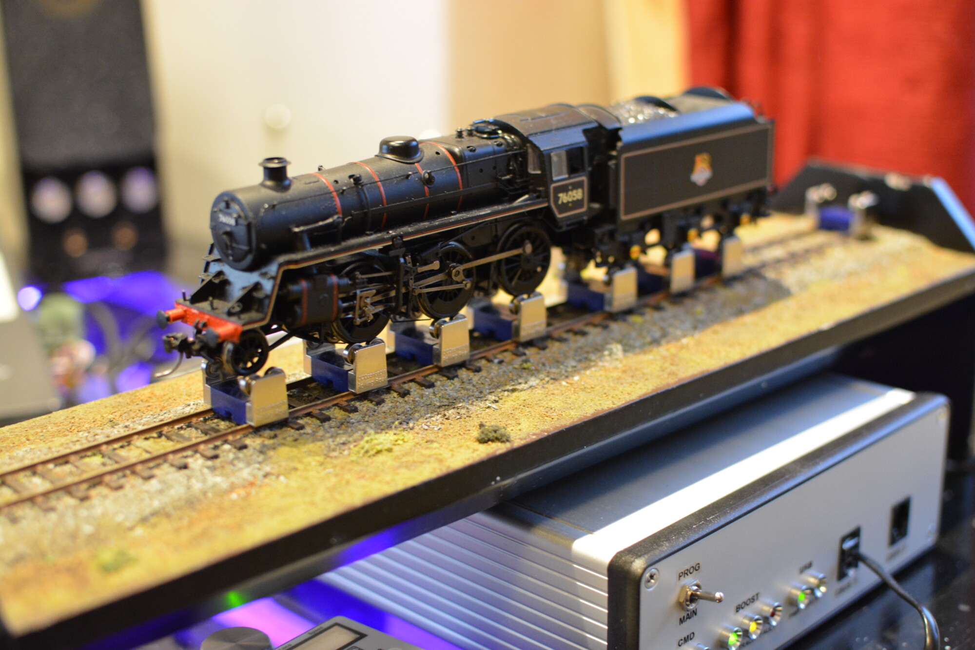
Below is a video of the finished locomotive running on the rolling road. It was quite a moment when it first started moving with sound; this is my first sound-fitted steam loco and it’s not something I’ve experienced first-hand before.
I’m pretty happy with the results – as is the norm for steam locos with sound I did have to spend about half an hour tweaking the “chuff rate”, in order to get the cylinder beats to be roughly in time with the wheel revolutions. As you can see in the video, the sync is not bad, but it is worse at some speeds than others. Reading around, it seems like this is pretty unavoidable, and the only way to truly stop this is to fit a so-called “cam sensor” to an axle, which would tell the decoder when to play the next cylinder beat. This sounds a bit too expensive and complicated for my liking, and to be honest the sync issue isn’t that noticeable, as I’ve tuned it to be more correct at speeds steps 30 and below.
Stay tuned for steam locomotive sound installations!