
Whilst I await the arrivial of my Hattons class 66 (update: delayed again due to axleboxgate!), I decided to fit my trusty old Bachmann 66 with a sound decoder. I’ve had the loco for about 10 years now and it’s always been a good runner, and the addition of a Zimo MX645 chip will not only add sound to the model, but also give me enough function outputs to run all the lights on their own separate function without the need for a second decoder. The sound project I’ll be using is from Digitrains.
I’ll also be fitting a large keep-alive, as I do with all my locos these days. Even though this loco picks up power from all 12 wheels, a keep-alive is still a good idea for reliablility.
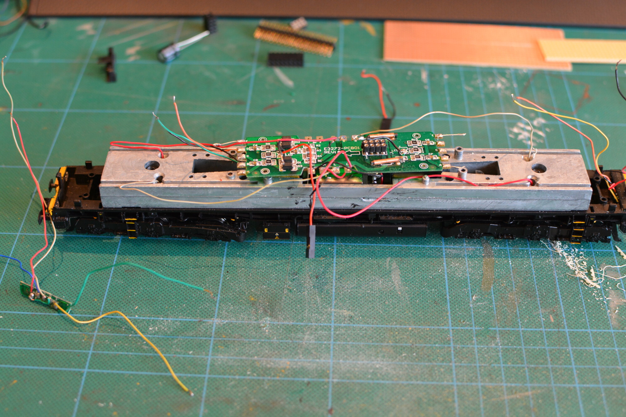
Removing the PCB
I’ll be removing the existing PCB for a number of reasons:
- It gives me more room to work with inside the body, as the replacement board I’ll be fitting will sit below the level of the lugs that the existing PCB sits on.
- I’m going to need eight function outputs from the decoder (top, right + left head-lamps and tail-lamps at each end). The 8-pin socket only supports three function outputs, so I’ll have to hard-wire five wires to the chip anyway, so I may as well dispense with the eight-pin socket and hard-wire the whole lot.
- In a similar vein, with my own board, I can easily add connection points for the speaker and keep-alive outputs on the decoder.
- Simplicity! Trying to trace what function output goes to what pin on the PCB is tedious and error-prone.
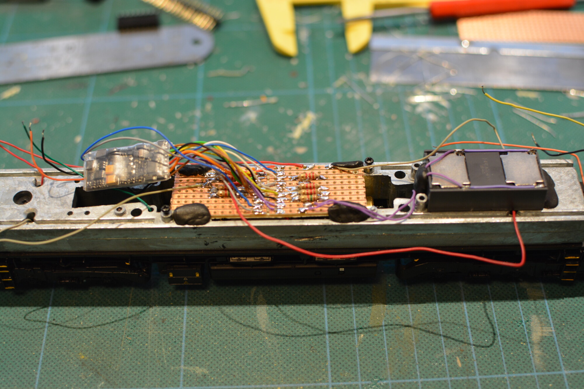
Installing the replacement PCB
All in all, I’ll need a total of eighteen connections between the decoder and the loco, so I’ve decided to use a piece of nine-way strip-board, cut down the middle to give eighteen zones. For the “pinout”, I’ll follow the standard DCC eight-pin arrangement, and add the extra ten connections below.
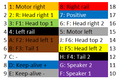
Each lighting output has its own current-limiting resistor (2.2kΩ for the six white head-lamps and 1.5kΩ for the tail-lamps). This makes it nice and easy to change the brightness of each individual function should I need to in future.
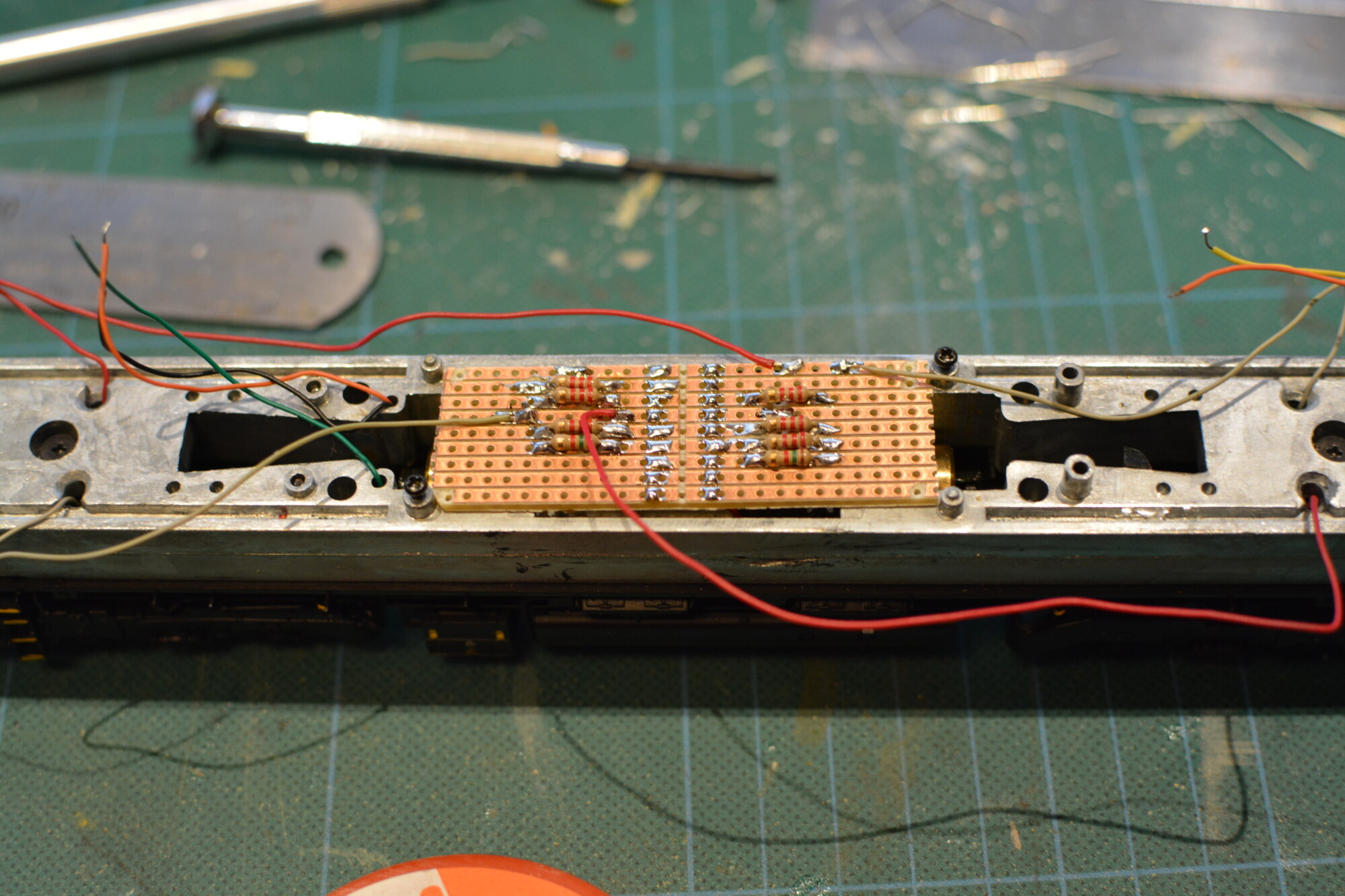
Connecting the components
Now it’s just a matter of making a lot of solder connections!
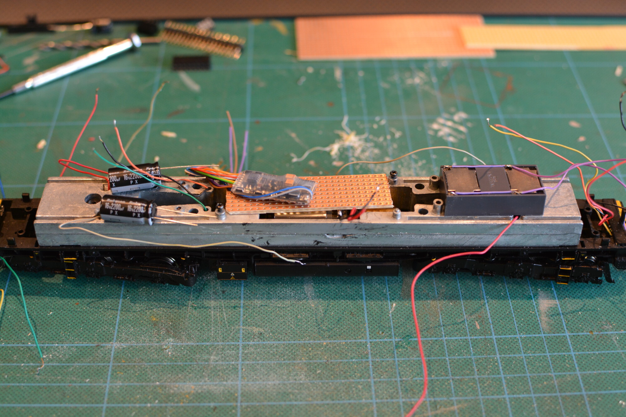
There’s just enough space for 3 2200μF capacitors behind the cab at the lead (no. 1) end of the loco. Connected in parallel, these give a total capacitance of 6600μF, which will be enough for about 1-2 seconds of operation when power is lost.
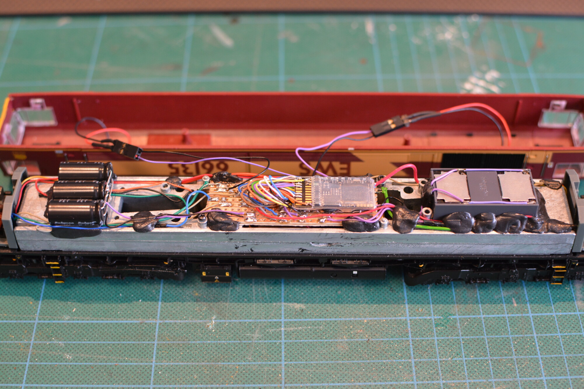
I’ve secured everything down using black-tack. This holds well (it’s much stickier than blu-tack) and is not permanent, so I can move or replace things if I ever need to. I applied a lot of it around the speaker to hold that down nicely and stop it rattling.