
One of the key features I want on Weybourne is working semaphore signalling. With the trackwork finished and the DCC and CBUS electrics installed, now seems like a good time to start looking at this.
Whilst at this year’s Tonbridge show, I saw a small layout that uses Dapol’s working signals and I was impressed. The owner of the layout in question explained how the signals, whilst they look pretty good (these were southen region style – perfect for Weybourne), the motor and control electronics leave a lot to be desired. The problems are:
- The motor is a worm drive, so cannot really change direction or speed rapidly enough to create that realistic “bounce” that most semaphore signals have when returning to danger.
- The signal is toggled by momentarily shorting two control wires together, as would be the case when connected to a push-button switch on a control panel. This is not very useful when I want to explicitly set the signal to either danger or clear, as I do not always know what state the signal is in before toggling it. This makes automation (see below) impossible.
Nevertheless, after some research online, I found that it’s relatively straightforward to replace the motor drive with a servo, which can then be configured move in any pattern I want, making animating bounces or other behaviours possible.
Automation
The signals on Weybourne will be fully automatic, meaning that the operator will never need to think about them. I want to do this because if it’s up to the operator to remember to set the signals, they will be forgotten. It should also be a fun challenge getting all the electronics working.
As per the prototype, there will be one signal per “departure road”, so three will be needed (for the bay platform, the main platform and the loop line). I will start with the signal controlling the loop line, as I am not sure what I will use for the ones for the two platform lines. In real life, two signals so close together would be mounted on a bracket, but Dapol do not produce a multi-arm signal in the SR style (only GWR). I plan to see how it goes with the first signal, then think about how I could make the platform signals work.
I’ll be using two kinds of electronic devices to detect whether a particular road is clear for a train to depart from:
- Track Occupancy Detectors. These monitor the current drawn by a particular block of track and can hence detect when a locomotive (or any piece of rolling stock that draws a current – more on this later) is in the block in question. These can be rather pricey if bought off-the-shelf, but luckily MERG have a “pocket-money” kit that that does the job for only £1.32. 🙂
- Turnout Position Sensors. A simple circuit that looks at the polarity of the turnout’s frog, and can then determine which way the turnout is set. Again, MERG offer a kit (actually the design is just four components) which I’ll be copying and adapting for my needs.
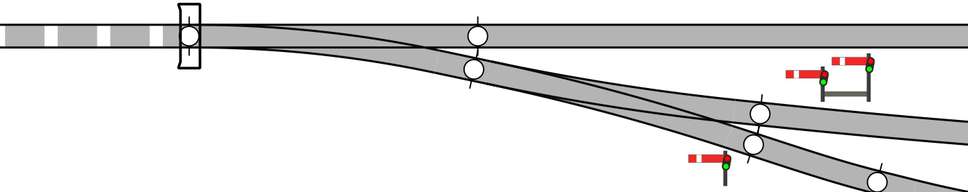
My plan is to use a combination of these two types of sensors to determine if a road is clear. For example, a train should be able to depart from the bay platform if (and only if) there is nothing in the hidden section, and the bay / main turnout is closed. The main platform and loop signals follow a similar logic, except that they need to also take into account which way the main / loop turnout is set. The table below sets out the conditions that must be satisfied in order for each signal to be set to clear.
| Signal | Track occupied | Bay / main turnout | Main / loop turnout |
|---|---|---|---|
| Bay | No | Bay | – |
| Main | No | Main | Main |
| Loop | No | Main | Loop |
Taking the loop signal as an example, the logic in the table is saying that it should only display clear when the track is not occupied, the bay / main turnout is set to main, and the main / loop turnout is set to loop. Because Weybourne is at the end of a single-track line, and all therefore all three departure roads feed into one, the logic is rather simple. From the table you can see that only one signal should be set to clear at a time.
Each of these sensors will feed into a control unit for each signal, and this unit will continuously monitor each sensor and update the position of the signal accordingly.
Solution design
Below is a diagram showing how the overall system will work. Here it is easier to see what sensors are connected to each signal controller.

Now it’s time to start building the various components!
Track block detection
The first piece I’m going to put together is the Track Occupancy Detector. This is a MERG kit that’s part of their “pocket-money projects” range – a set of simple electronics kits that are easy to put together and cost very little.
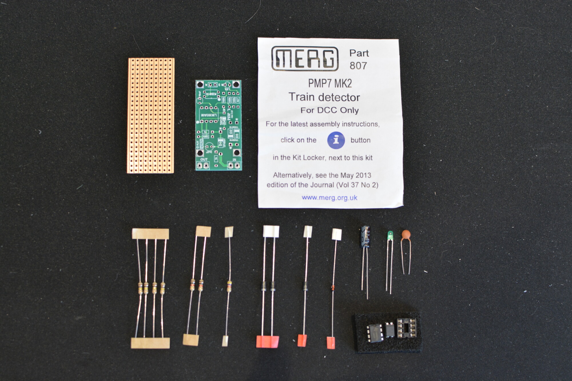
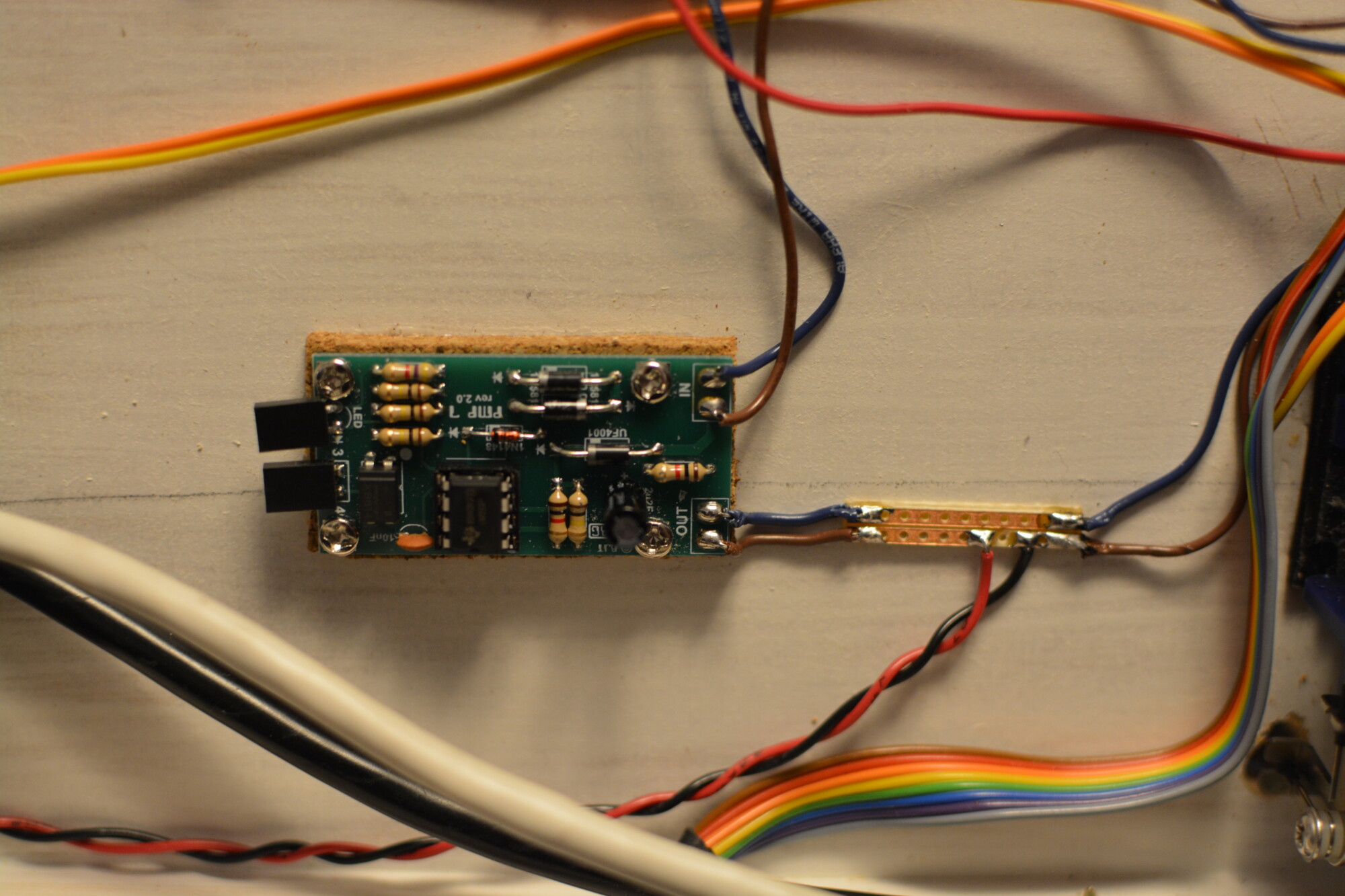
The Track Occupancy Detector is placed between the DCC bus and a section of track, and works by detecting current drawn by a locomotive or piece of rolling stock. On DCC, even a loco that is not moving draws a small current to power its decoder. When a current is drawn in the track section, a pair of diodes start to emit a stream of pulses, which cause a capacitor to charge, which in turn switches on an opto-isolator. When this isolator is on, it has a low resistance, and therefore behaves like a switch, meaning it can be “read” to check if anything is on the track.
The kit is one of the simpler MERG kits to put together, with only a small number of through-hole components to fit. It took about 20 minutes to assemble and test. As I mentioned earlier, I’m using the dedicated PCB that MERG sell separately, rather than the piece of 9×25 stripboard that comes with the kit.
Turnout position detection
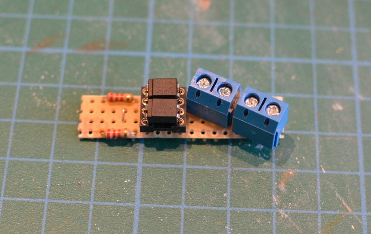
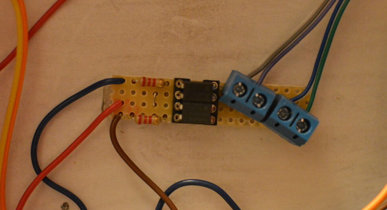
The Turnout Position Sensors are an even simpler design. In fact the design is so simple (basically only two components are required) that I chose source to the components and build them myself instead of buying kits.

The sensor works by connecting the input side of one of the bi-polar opto-couplers (the KB814s) across the left rail and the frog feed, and the input side of the other opto-coupler across the right rail and the frog. Because the point motors I’m using switch the polarity of the frog for me when throwing the turnout, we can use this to detect which way the turnout is set.
When the turnout is closed (set to left), the frog will be fed from the right rail, meaning there will be a difference in voltage between the left rail and the frog, and no difference between the right rail and the frog. This difference will cause a current to flow through the LEDs in the opto-coupler connected across the left rail and the frog, which will cause a low resistance across the opto-coupler’s output, effectively turning it on, just as if a physical switch had been closed. The process is identical for detecting when the turnout is open (set to right), except that the opto-coupler’s input is connected to the right rail and the frog.
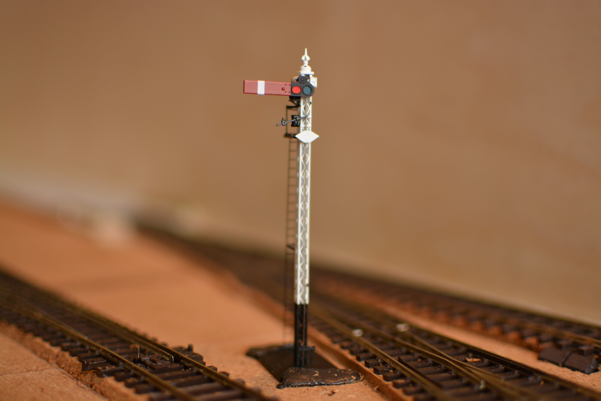
Converting the signal to use a servo
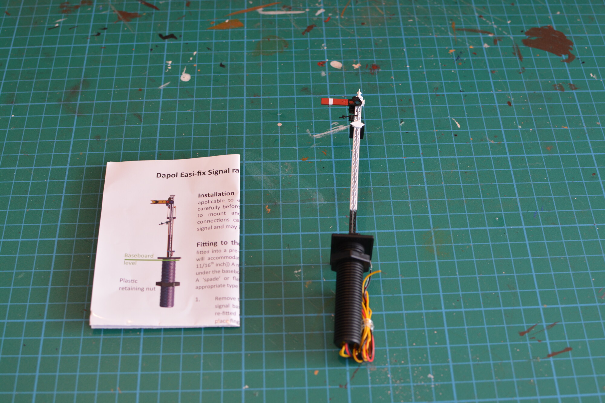
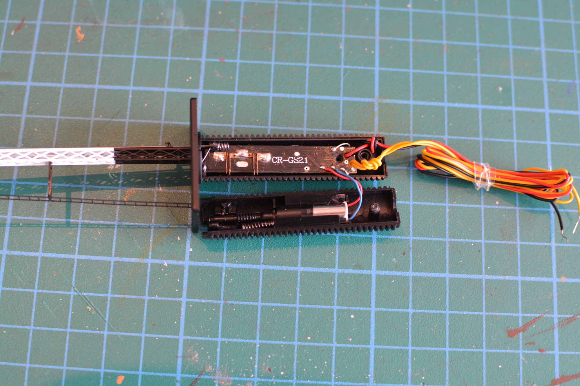
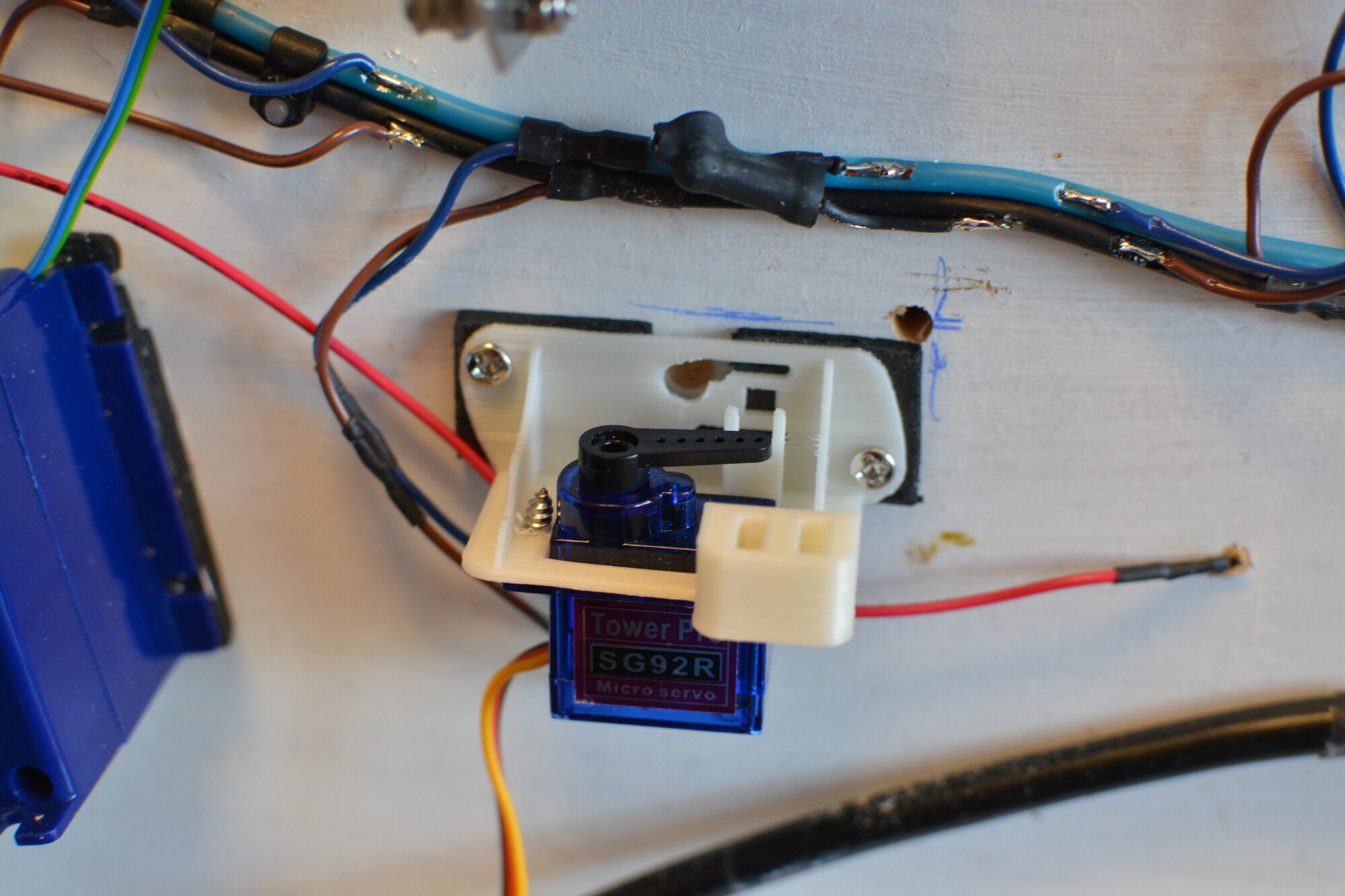
Whilst this project makes use of a lot of electronics, there is some mechanical work to be done: namely converting the Dapol signal to use a standard hobby servo instead of the provided worm drive. Servos are better suited to this task than a normal DC motor because they can be instructed to move quickly and accurately to a specified angle, thus allowing me to animate the movement of the signal arm pretty much however I choose. The particular type of servo I’m using is the Tower 92R, a typical low-cost 9-gram servo. I’m sure there are better servos available, but this was cheap (around £5) and will do me for now.
The first step is to remove the existing mechanism. Its a shame to not be using the motor and gearing that I paid for, but I might find a use for it in the future. I began by removing the plastic nut from the outside, and then unscrewing a small screw near the bottom that holds the two pieces together.
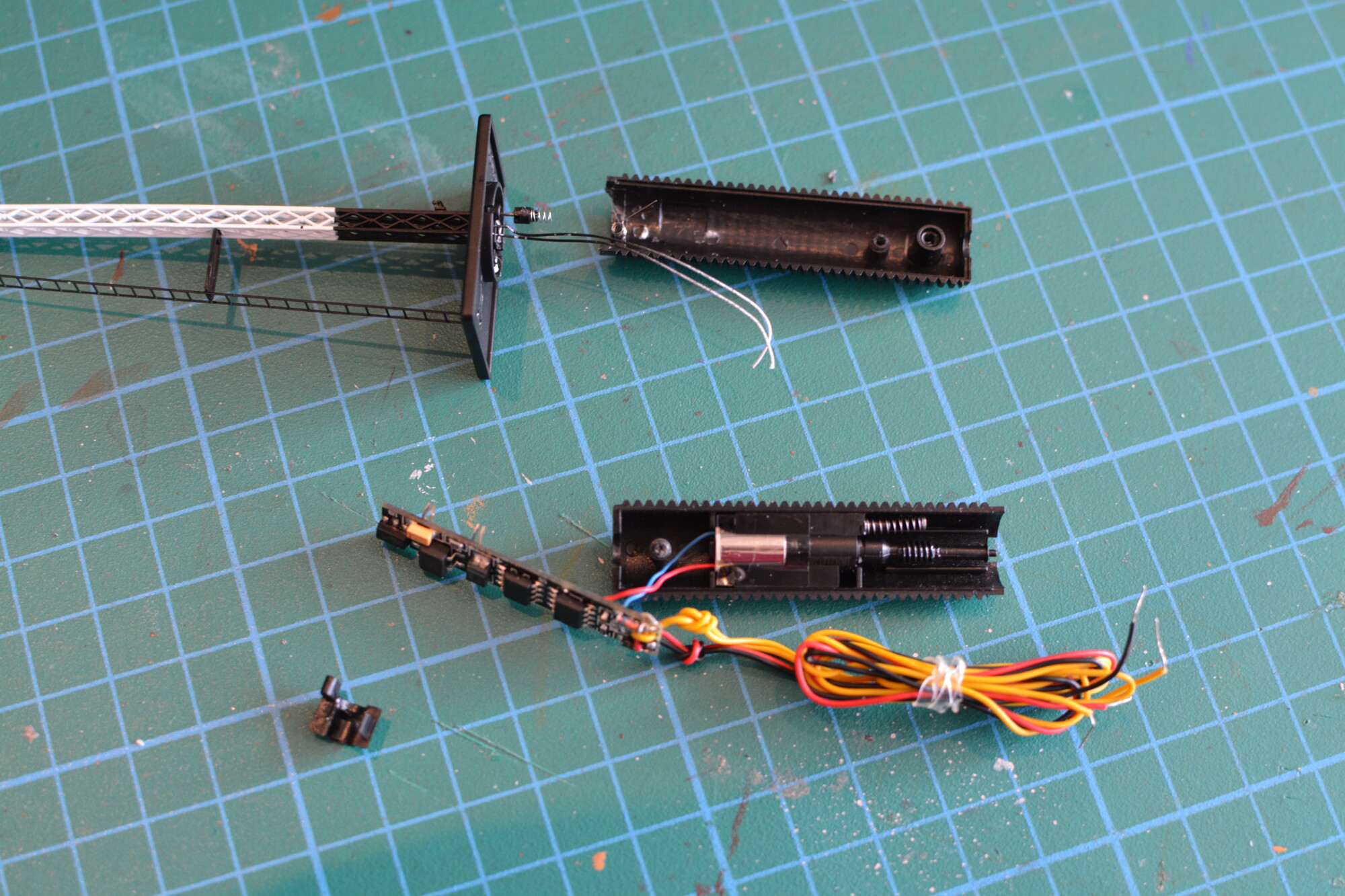
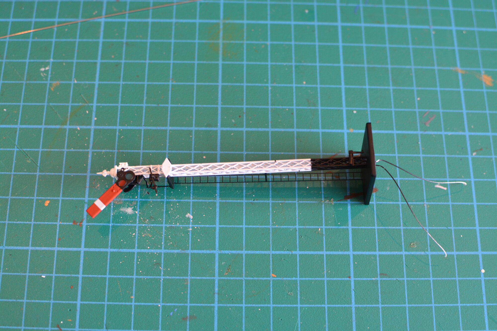
Once the old mechanism has been removed, a new length of 0.5mm wire was installed, and the signal is ready to install on the baseboard!
With the signal test-fitted on the baseboard, I removed it again and headed underneath to mount the servo, using a 3D-printed servo mount from MERG. This made fitting the servo extremely easy, and was definitely worth the £1 or so I spent on it!
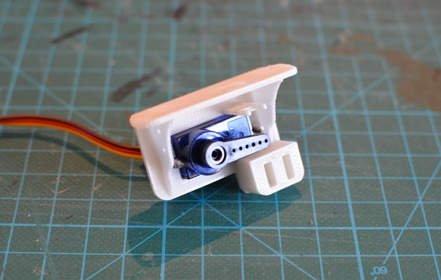
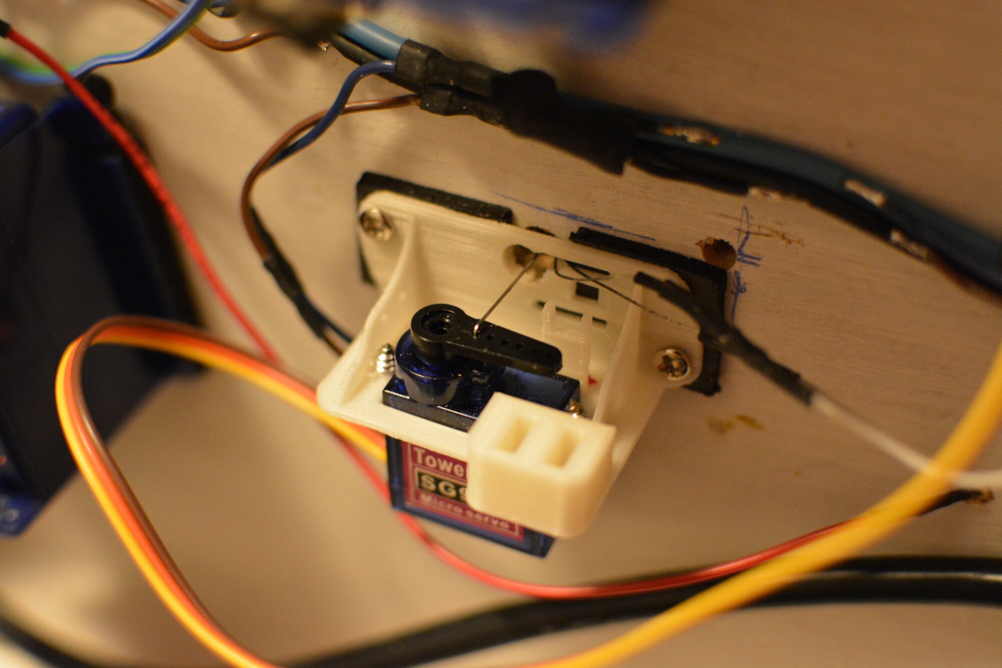
The servo arm needs about 3mm of travel in total, so I’m going to use the hole on the servo arm closest to the shaft. This will give the smallest amount of travel and the maximum effective speed will be reduced, but the movement will be smoother and more precise, which is what matters.
The final step is to fit the signal in place again, carefully feeding the rod through the hole and cutting it off a few mm past the servo arm. All I need to do then was set the signal arm to danger (horizontal), set the servo arm to roughly horizontal and bend the rod 90 degrees where it lines up with the hole in the arm, using a pair of pliers. I then threaded the bent part of the rod through the servo arm, and, once through, bent it a bit more to prevent it from popping out for any reason.
Controlling the servo
The biggest part of this project is the servo controller. This will take input from one or more of the sensors, and use the state of these inputs to determine whether the signal servo it is controlling should be set to danger or clear. It will also be responsible for moving (or animating) the servo in a realistic way. Each servo will require one controller. The controller will also supply power to the signal’s LED.
The electronics
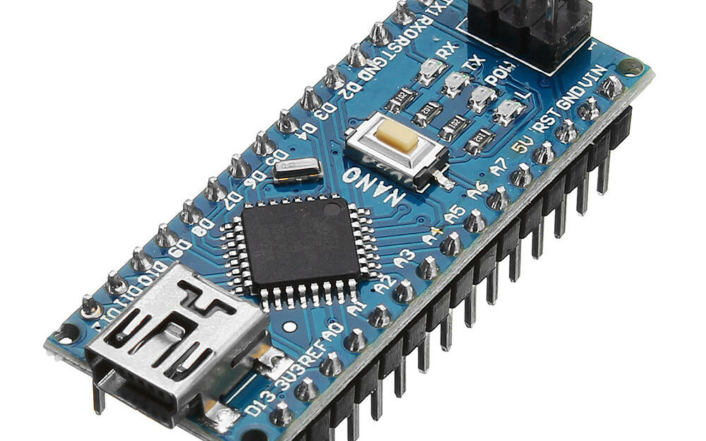
The servo controller will be based around an Arduino microcontroller board, which will be performing essentially just two tasks: Reading the sensors and animating the servo. I’ll be using the Nano variant, which is plenty powerful enough for what I need, and cheap enough (Nano clones can be bought for less than £3) that I can use one per signal to make things easier.
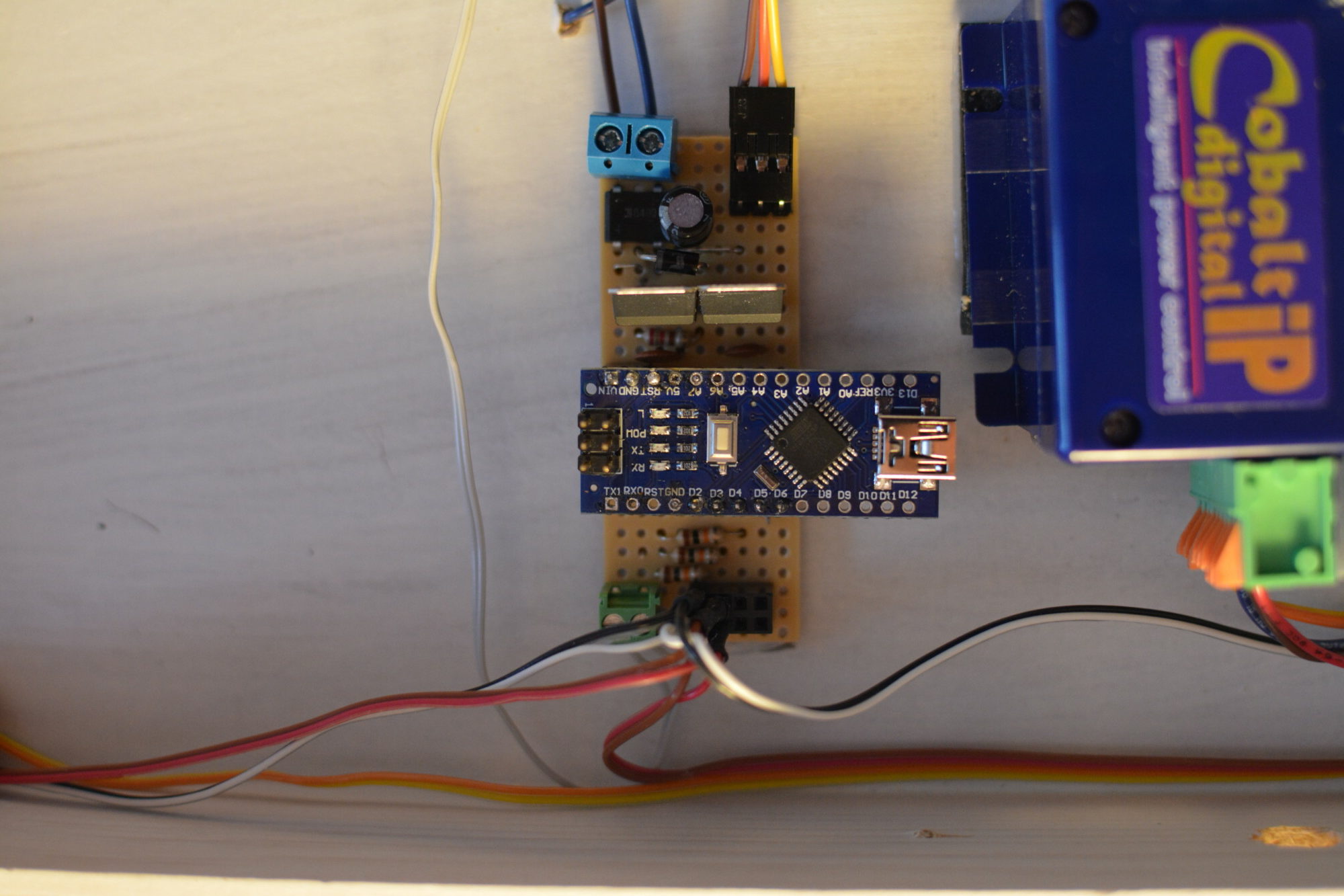
The Arduino will need a 7-12 VDC supply, plus connections to each of the input sensors and the servo. I’ve therefore designed a simple circuit that fits on a piece of 25 x 9 stripboard.

In the top-left we have a bridge rectifier that will convert AC (or bipolar DC – which is what DCC is) to DC. It will also work if suplied with straight DC, but the ability to run off any supply means I can power it either from the DCC bus or from a separate supply. Connected to this there is a 220μF capacitor, which is there to smooth out any ripples in the output from the rectifier. This capacitor has a resistor-diode pair in series with its positive terminal – this reduces the inrush current when the capacitor is charging, whilst allowing it to discharge as fast as is required.
After the capactior, the smoothed DC is then fed into two linear voltage regulators. These will supply 9V and 5V to various components:
- 9V will be fed to the Arduino’s VIN pin, which is capable of accepting 7-12V.
- 9V will also be supplied to the 2-way terminal in the bottom left. This is where the signal’s LED will be connected.
- 5V will be supplied to the servo, in the top-right.
- 5V will also be connected to one side of each sensor input (more on this later).
The two regulators have 10nF capacitors connected across their outputs, which helps to reduce ripple in the output, which the Arduinos (or at least the clones I bought!) seem to be sensitive to. I managed to corrupt two of them before I realised a noisy power supply was to blame. Luckily I was able to re-program them using another Arduino as a dedicated programmer. 😎
The Arduino will connect to the board by way of the 2-way and 5-way sockets in the centre third of the board. The 2-way header on the left will connect it to 9V and ground, and the 5-way header will connect to the 4 sensor inputs and the servo control pin (the yellow wire in the digram).
In the bottom right there is a 2×4-way socket where up to four sensors can be connected. A pull-down resistor connects the Arduino input pin for each sensor input to ground, as well as to one side of the sensor input socket (the white wire in the case of sensor input 4), meaning that until the sensor is activated, the Arduino “sees” 0V (low logic level). The other side of each input (the orange wire in the case of sensor input 4) is connected to 5V (or high logic level). When the sensor is activated, it drives its output low, connecting both sides of the sensor input, thus exposing the Arduino’s input pin to 5V. We can detect this in the code running on the Arduino.
The Arduino code
Whilst the code for the signal controller isn’t complex by Arduino standards, it’s still around 350 lines, so I won’t post it all here. I’ll describe the overall design and then focus in on some of the more important pieces. A full copy of the source code can be found on GitHub.
Design
The code loops around a simple state machine, waiting for input from the sensors and moving the servo accordingly.

Setting up
At the top of the file, we define what pins we will use for the sensor inputs and servo control.
#define PIN_TRIGGER_A 2
#define PIN_TRIGGER_B 3
#define PIN_TRIGGER_C 4
#define PIN_TRIGGER_D 5
#define PIN_SERVO 6
Then, inside the setup() function, we set up these pins ready for use.
// Setup input pin(s)
pinMode(PIN_TRIGGER_A, INPUT);
pinMode(PIN_TRIGGER_B, INPUT);
pinMode(PIN_TRIGGER_C, INPUT);
pinMode(PIN_TRIGGER_D, INPUT);

// Setup the servo(s) for the signal(s)
signalServo.attach(PIN_SERVO);
The main loop
Inside the loop() function (which runs after setup() and continues until the board loses power), the state machine from above is implemented using a series of functions that run one after the other.
void loop() {
  // Wait for "danger" to be requested.
  waitForDanger();
  // Set the signal to "danger".
  setToDanger();
  // Wait for the minimum danger time.
  waitForMinimumDangerTime();
  // Also wait until "clear" is requested.
  waitForClear();
  // Return the signal to "clear".
  setToClear();
}
Reading from sensors
As on the real railway, the signal should only be set to clear if the entire route is clear. As soon as one sensor reports danger, the signal is set to danger. This is achieved in the code by using a series of logical OR statements, so that if any of the sensor pins report a high logic level, danger is set.
boolean isDangerSet() {
  return isPinHigh(PIN_TRIGGER_A) || isPinHigh(PIN_TRIGGER_B) || isPinHigh(PIN_TRIGGER_C) || isPinHigh(PIN_TRIGGER_D) ;
}
Waiting for events
We wait for things to happen using the usual Arduino approach: looping around ad infinitum until the condition we are waiting for is true (we check this condition on line 4 below). Additionally, we want to prevent transient events from triggering a state of state (for example a human hand or foreign object touching the rails momentarily for a few milliseconds should not cause the signal to be set to danger). We do this by checking the condition every 10ms (line 8), and only leaving the loop when the condition has been true for the last 50 checks (line 3). This means that, for the “danger” example below, danger will only be set when isDangerSet() has been true the last 50 times it was checked (half a second).
void waitForDanger() {
  int count = 0;
  while(count < DANGER_SAMPLE_COUNT){
    if(isDangerSet()){
      count++;
    }
    else count = 0;
    delay(TRIGGER_SAMPLING_INTERVAL);
  }
  return;
}
Controlling the servo
To simplify things, all calls to move the servo go through one function: setServo(). This uses the more accurate Servo.writeMicroseconds() function, which gives us sub-degree precision. I’ve also added some safety checks here that ensure we never try to move the servo past the boundaries of normal movement, as this would break the signal mechanism.
void setServo(Servo servo, float degrees) {
  // Sanity-check the angle we are setting so we don't break the signal!
  if(degrees < servoMinAngle){
    degrees = servoMinAngle;
  }
  else if(degrees > servoMaxAngle){
    degrees = servoMaxAngle;
  }
  servo.writeMicroseconds(degreesToMicroseconds(degrees));
  currentServoAngle = degrees;
}
Animating the servo
Of course, simply moving the servo between the clear and danger angle as fast as possible would look terrible and shorten the lifetime of the signal mechanism by placing it under stress. We therefore need a way of slowing down the movement and introducing more complex animations, like bounces or smooth changes in speed. The function below achieves this by looping for a pre-determined time (around 1-2 seconds) and updating the servo angle every 10ms (so 100 times a second).
void animateServo(int startAngle, int endAngle, int durationMs, float (*function)(float)) {
  int sweepAngle = endAngle - startAngle;
  int nSteps = round((float) durationMs / (float) SWEEP_STEP_INTERVAL);
  float stepAngle = (float) sweepAngle / (float) nSteps;

  float sweepFraction, interpolatedSweepFraction;
  for (int i=0; i<=nSteps; i++) {
    sweepFraction = (float) i / (float) nSteps;
    interpolatedSweepFraction = (*function)(sweepFraction);
    setServo(signalServo, startAngle + (sweepAngle * interpolatedSweepFraction));
    delay(SWEEP_STEP_INTERVAL);
  }
}
As it stands, the above code will animate the servo from the start angle to the end angle, over the specified period of time. However, the servo angle will be linear all the way from the start angle to the end angle, which will not look very realistic. To improve on this, the function is provided with an interpolator when called. This interpolator is tasked with the job of returning the desired positional fraction (from 0 to 1) for a given input fraction (also from 0 to 1). In short, this interpolation function allowsus to re-map the raw angle we started with to something else. An example of a simple smoothly-accelerating and decelerating interpolator is shown below:
float accelerateDecelerateInterpolator(float fraction) {
  return (float)(cos((fraction + 1) * PI) / 2.0) + 0.5;
}
This interpolator can be used to smoothly animate the signal arm from one position to another. I have written several interpolators, all with slightly different behaviours – some start off slowly and accelerate before stopping suddenly (to simulate the signalman pulling the lever back quickly), some have bounce built-in (for when the signal returns to danger and the arm bounces), and there’s even one that has a pause mid-way through, as if the signalman took two goes to pull the lever.
Randomising the animations
To make the signal’s movements appear even more realistic, we can define several different interpolators and choose one at random when animating the servo between clear and danger:
void setToDanger() {
  // Catch the edge case where the servo may already be set to danger
  // (this will occur once after startup if isDangerSet() returns true during setup()).
  if(currentServoAngle==SERVO_ANGLE_DANGER){
    return;
  }
  digitalWrite(PIN_LED_DANGER, HIGH);
  // Pick a random animation from a set of 4.
  int animationNumber = rand() % 4;
  switch(animationNumber) {
    case 0:   // Animation 1: One bounce, fast decay.
      animateServo(SERVO_ANGLE_CLEAR, SERVO_ANGLE_DANGER, getRandomDelayMs(1200, 1400), oneBounceInterpolator);
      break;
    case 1:   // Animation 2: Two bounces, medium decay.
      animateServo(SERVO_ANGLE_CLEAR, SERVO_ANGLE_DANGER, getRandomDelayMs(1300, 1500), twoBounceInterpolator);
      break;
    case 2:   // Animation 3: Three bounces, slow decay.
      animateServo(SERVO_ANGLE_CLEAR, SERVO_ANGLE_DANGER, getRandomDelayMs(1400, 1600), threeBounceInterpolator);
      break;
    default:
    case 3:   // Animation 4: Three bounces, alternative algorithm.
      animateServo(SERVO_ANGLE_CLEAR, SERVO_ANGLE_DANGER, getRandomDelayMs(1300, 1600), fixedBounceInterpolatorOne);
      break;
  }
}
Now the servo will be animated using one of four different interpolators, and the duration of the movement will also be chosen at random.
Sequencing multiple signals
In real-life, signals are operated by a signalman moving a lever in the signal box. Since each signal has its own separate lever, you would never see two signals moving at the same time. This is easy to achieve by using a random delay based on a sequence number:
// Sequence delay
#define SEQUENCE_NUMBER 0
#define SEQUENCE_DELAY 3000   // 3 seconds between each signal moving.

void sequenceDelay(){
  delay(SEQUENCE_NUMBER * SEQUENCE_DELAY);
}
As long as each signal controller has a different SEQUENCE_NUMBER, we can ensure that no two signals are moving simultaneously by calling sequenceDelay() before animating the servo.
Demonstration and final thoughts
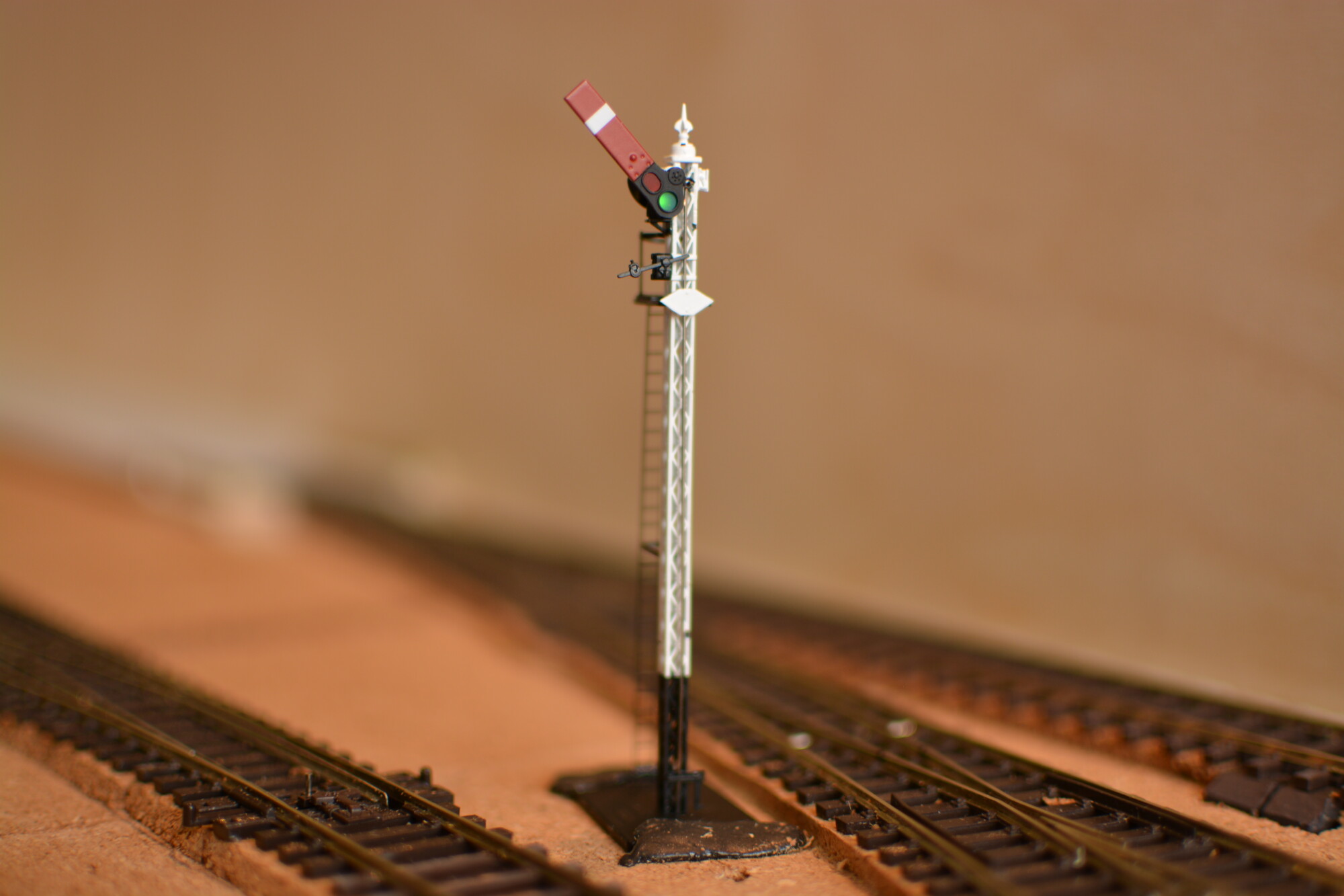
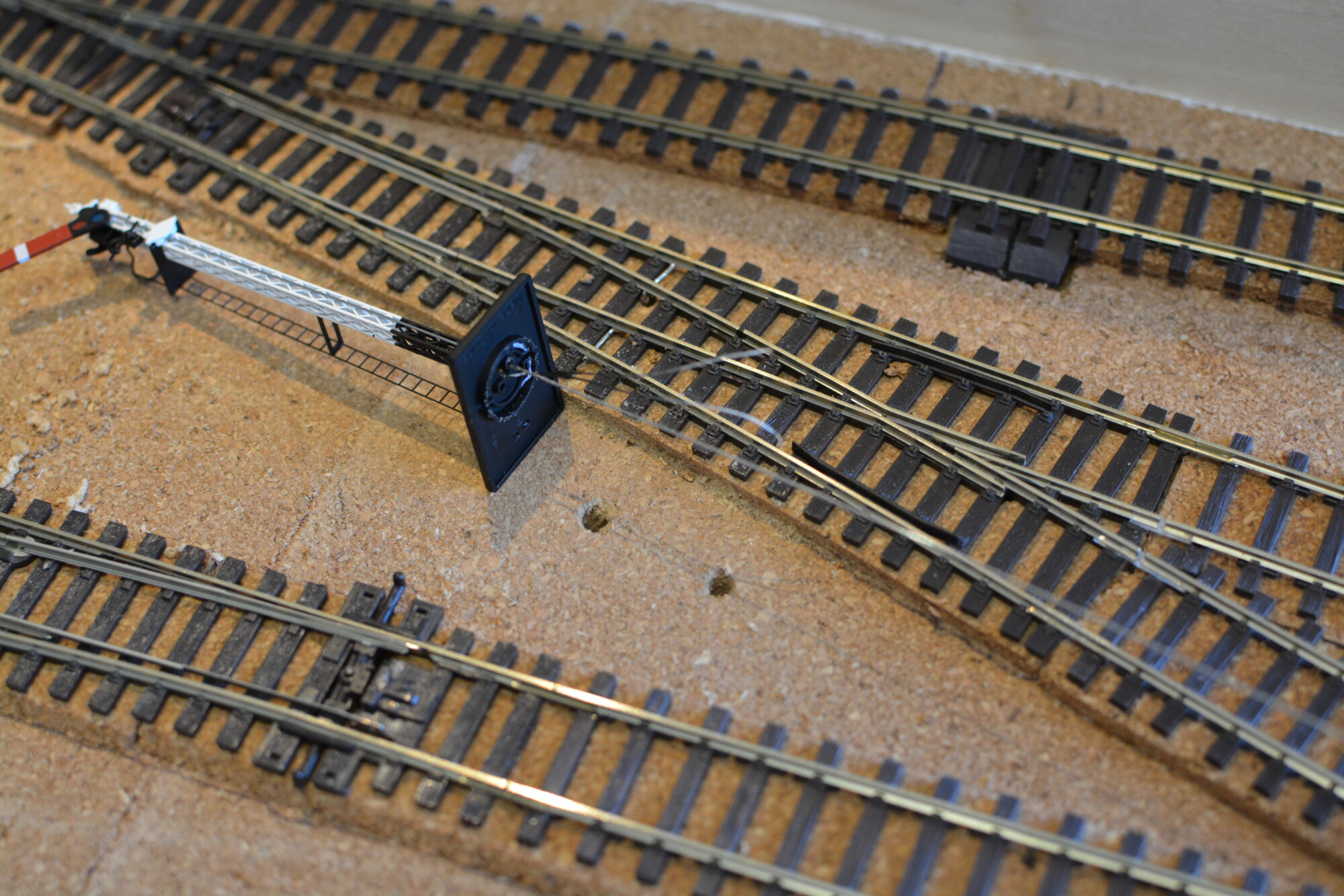
Below is a short demo of the detection system at work.
The sequence of events you see is as follows:
- Initially the signal is at clear, as there is nothing on the track to the left, and both points are set to the “loop” road (the signal is for the loop road).
- When the loco moves into the section of track that is monitored (shown by the orange pen), the signal moves to danger.
- When the far point (“bay” / “main”) is closed and the loco moves into the “bay” road, the signal remains at danger, because the “bay” / “main” point is set against the “loop” road.
- When the “bay” / “main” point is thrown, the signal returns to clear, as both points are now set to the “loop” road again.
- When the “main” / “loop” point is closed, the signal returns to danger, as the “loop” road is blocked once more.
- When the “main” / “loop” point is thrown, the signal returns to clear, as both points are now set to the “loop” road again.
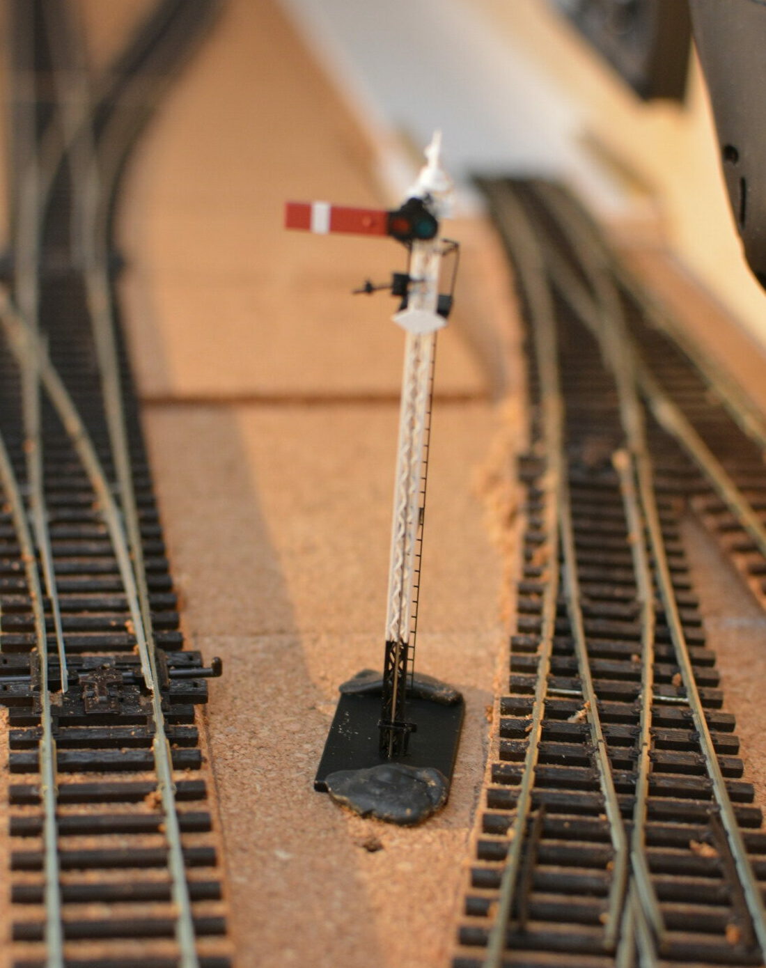
This project turned out rather well – the signal operation appears to be reliable and I think it looks quite authentic. I will tweak the bouncing animations a bit to make them look more realistic.
The next stage is to install the main and bay signals. These will present a new challenge, as I want to mount them on a single bracket, as they would be in real life. Watch this space for the next update!