
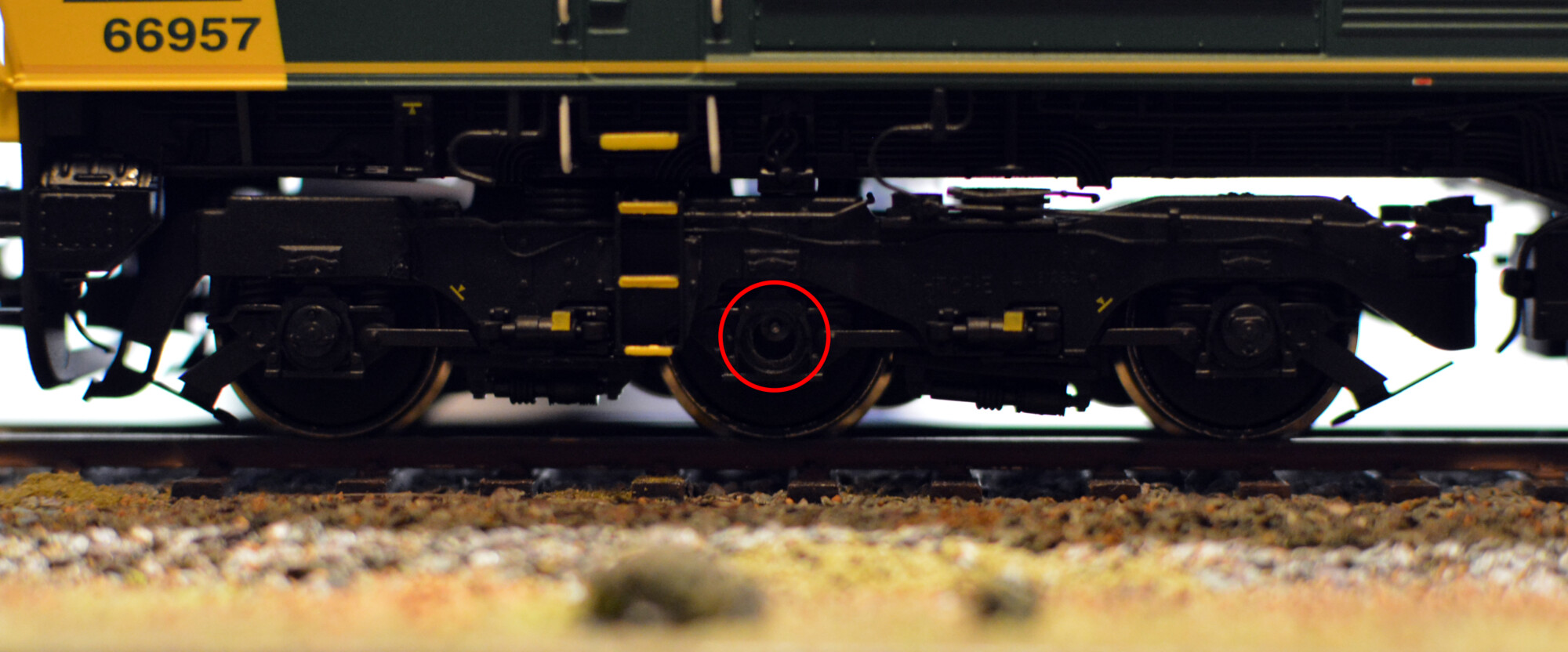
Out of the box, neither of my Hatton’s 66s run smoothly, due to the rotating axleboxes not being aligned correctly with the holes in the bogie frames. This means that when the wheels rotate, the axlebox either works itself loose due to it constantly being pushed towards the centre of the hole in the bogie frame, or, if it is glued on firmly enough, it actually pushes the bogie frame up and down as the wheel rotates. Neither of these are good options – especially for such a fantastic model overall.
In this post I’ll describe the steps I’ve taken to correct the issue on my two examples. From start to finish the process took me between one and two hours and was well worth it to complete this excellent model.
It’s worth pointing out these steps are what worked for me, and your mileage may vary, depending on how your model runs and how it was assembled. From what I’ve read online the axlebox problems are a bit of a lottery, with the majority of examples being pretty good, and a relatively small number having more severe problems.
This misalignment is caused by a combination of the following:
- An optimistic bogie design. For the axleboxes to rotate perfectly, the inner bogie stretcher needs to be at exactly the right height relative to the wheels, otherwise the holes in the stretcher will not line up with the axles, and they’ll rotate off-centre and eventually fall off. I say optimistic because for it to run perfectly, all the wheelsets need to be seated properly, the outer bogie frame must sit true with respect to the mechanical inner part of the bogie, and the stretcher should push up fully inside the outer bogie frame. If all these conditions are met, then the axleboxes will rotate just fine and are much less likely to fall out over time. If any one of these is not however, then you have a problem!
- Lack of a decent attachment between the wheel and the axlebox itself. Each axlebox is pushed onto a small spigot on the wheel and held on with glue, but a moving part like this should really be attached with a thread or something a bit more permanent.
- Varying assembly and quality-control in the factory. This seems to be a bit of a lucky dip to be honest – 66789 was atrocious (glue everywhere, some axleboxes even glued to the frame and not the wheel), but 66957 was on the whole pretty good.
Removing the axleboxes
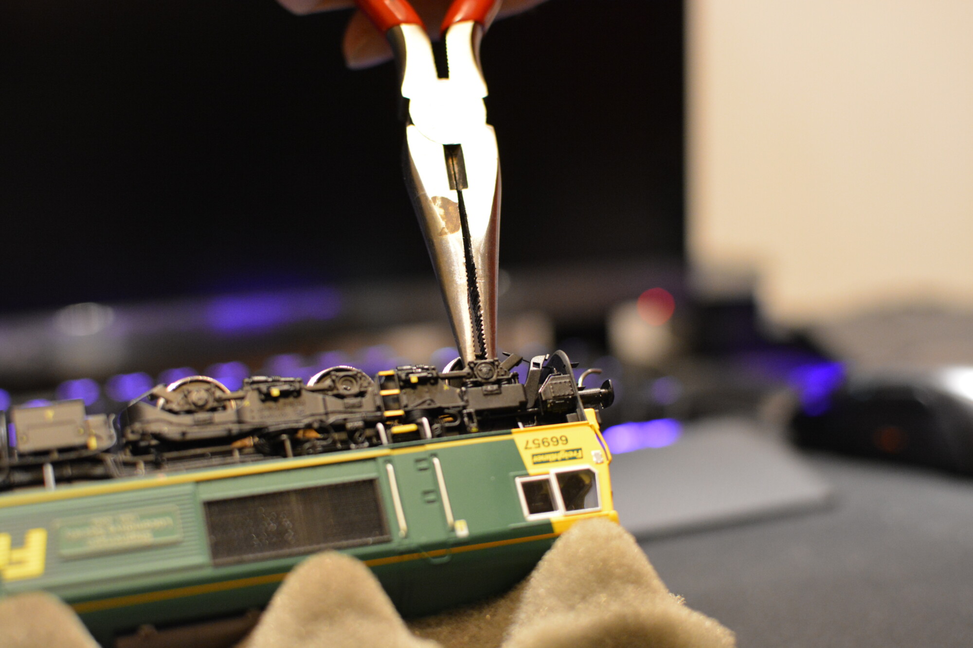
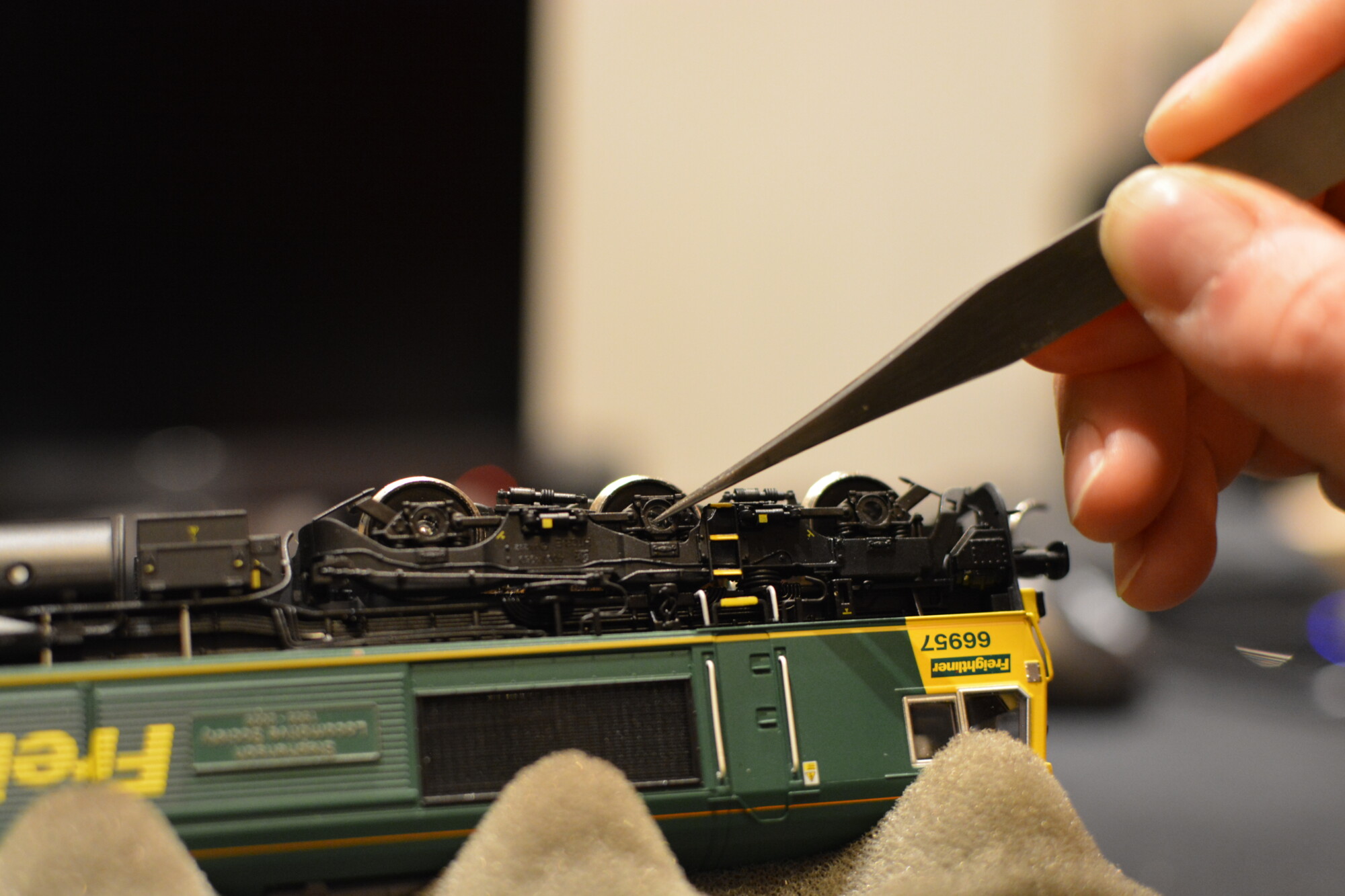
First things first, the axleboxes need to be removed. This is necessary because they fit through holes in the inner bogie frames, so these frames cannot be removed with the axleboxes in place. Removing the axleboxes is straightforward – grip the shaft with a pair of points and, whilst holding the wheelset to prevent it from moving, turn the points until you feel the axlebox “give” and start to rotate on its own.
Fixing the inner bogie frames
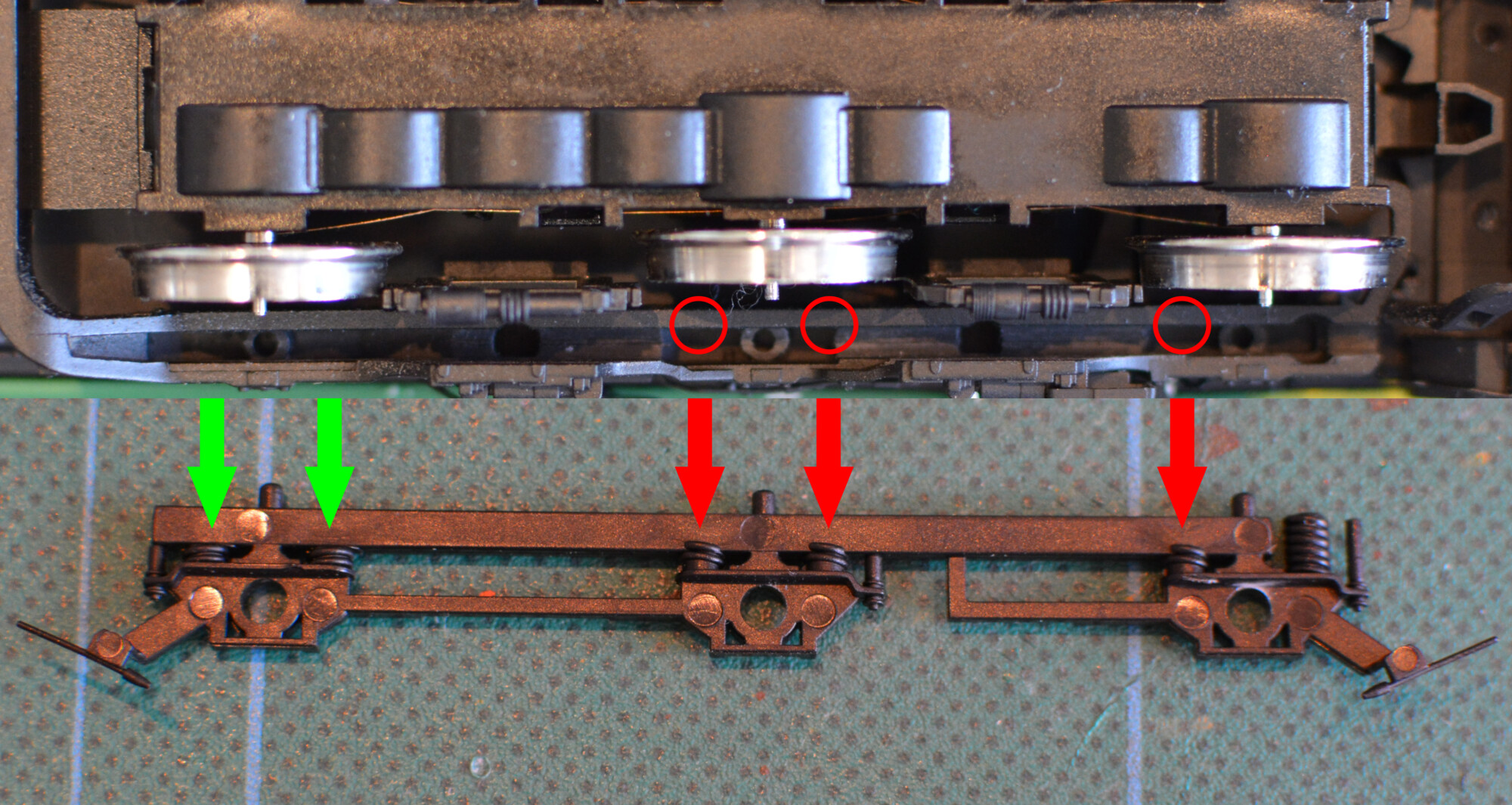
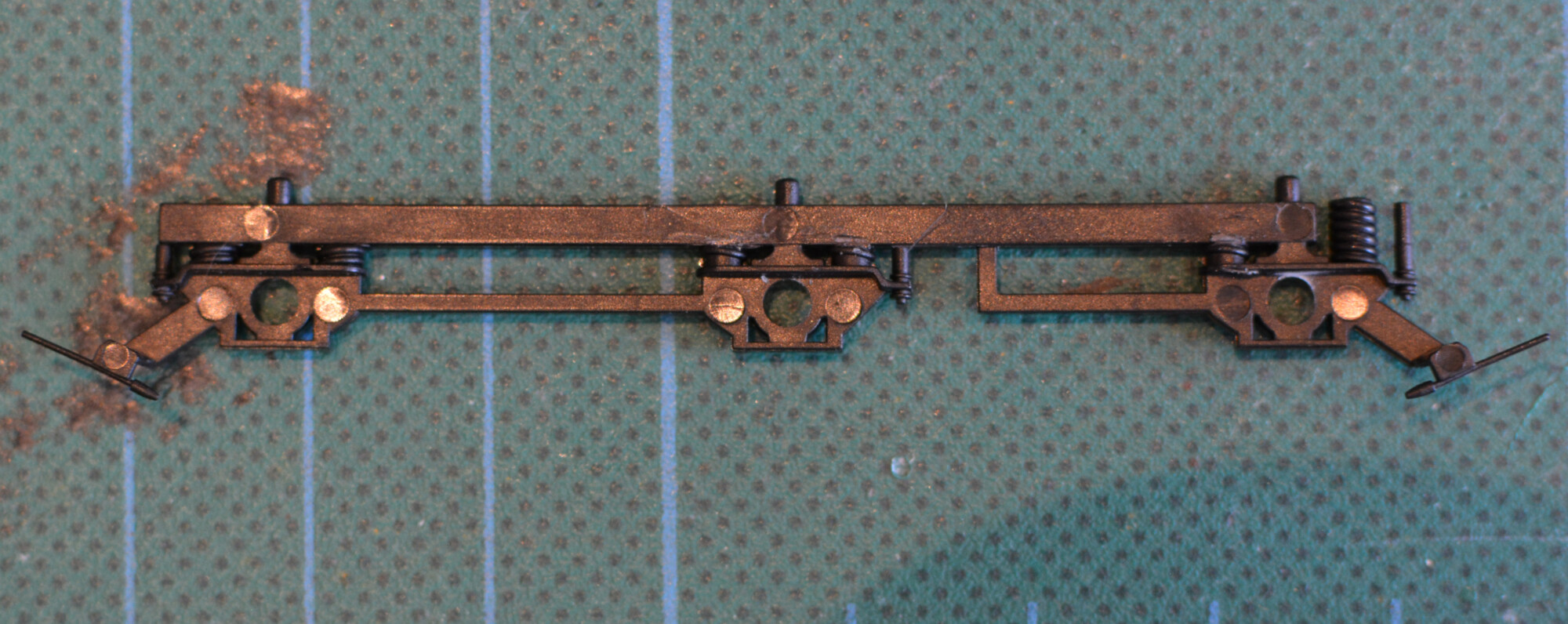
With the axleboxes removed, we can see the problem: the holes in the bogie frame do not line up with the spigots on the wheel. Looking at the photo below, we can see that the inner frame does not go all the way up inside the main bogie frame, resulting in the hole being too low relative to the axle itself.
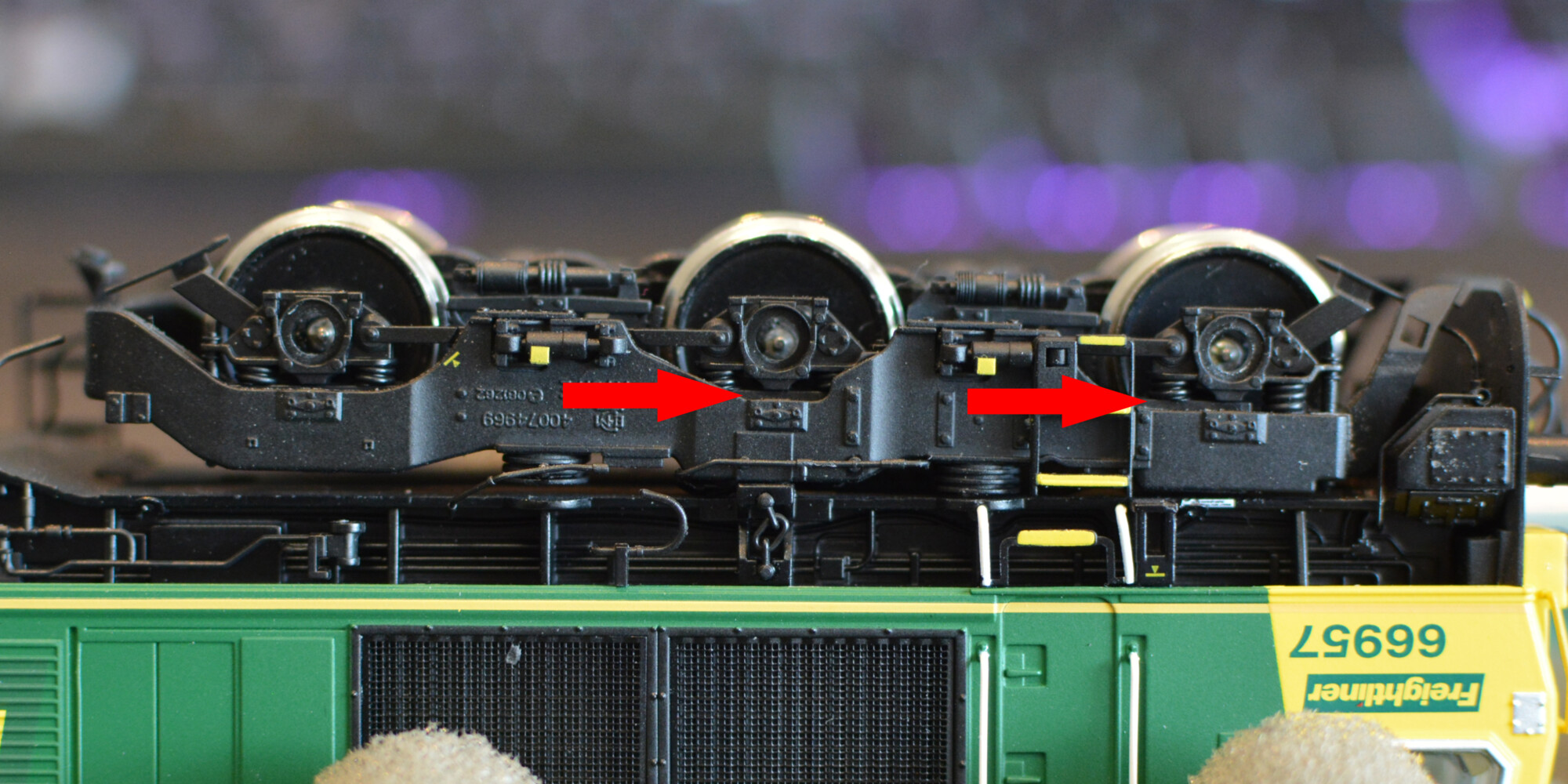
Interestingly, on this loco there are two problematic bogie frames, one on each bogie, and both on the same side of the bogie. In each case, the innermost axle is fine, but the centre and outermost ones are affected. Is this a coincidence? Let’s find out!
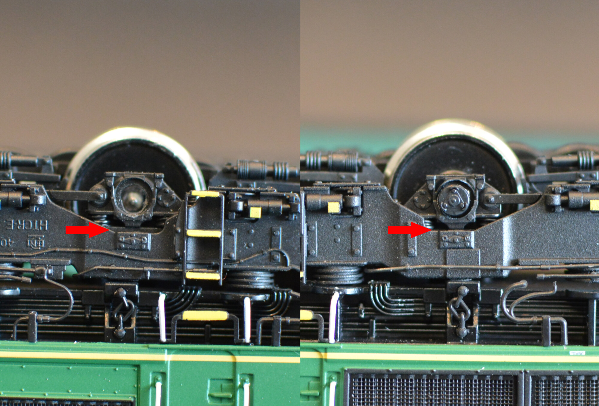
Now we can see the cause of the problem! On the inside of the frame, the moulding for the springs has been continued above the bottom of the main horizontal bar. Since this bar is meant to fit entirely inside the bogie frame, these tiny extra moulding details stop the inner bogie frame from locating properly.
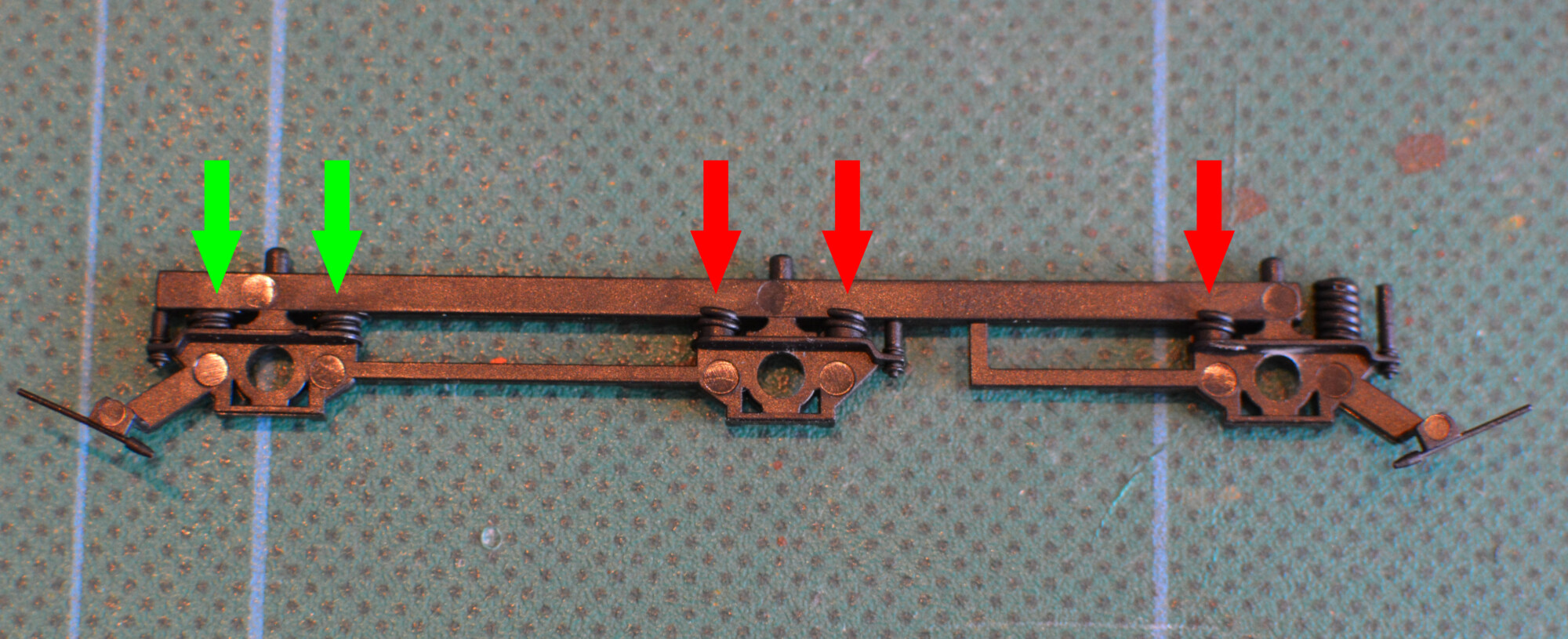
The composite image below shows what’s happening – these three moulded springs will catch on the inside of the “trough” that the inner bogie frame is supposed to locate into.
Let’s have a look at an inner bogie frame from the right-hand side. Here we see that the spring moulding does not continue onto the main bar, and therefore the frame can locate properly.
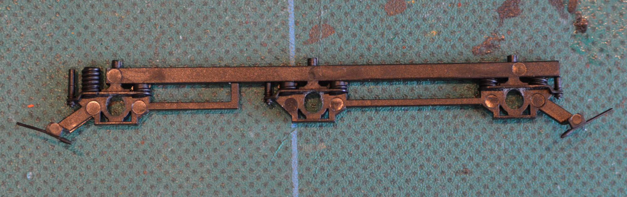
I checked all four inner bogie frames, and the same pattern is repeated: the two left-hand ones have the extra moulding, whereas the two right-hand ones do not. They must be separate moulds, since the large springs (on the left in the photo above) are on the outer edge of the bogie, so therefore two moulds are required – one for each side of the bogie.
I can only conclude that the spring detail must have been present on both at one point in time, and then removed from one (perhaps when a potential problem was discovered), but mistakenly kept on the other.
Since we now know what the problem is, and because the extra detail is totally hidden when the inner frames are fitted, the fix is easy: shave off the extra detail with a scalpel:
Increasing the hole size
Just to be on the safe side, whilst the bogies are dissassembled, I’ll also take the chance to open out the holes just a fraction, as a “belt and braces” approach to ensure the loco runs well.
Shortening the axleboxes
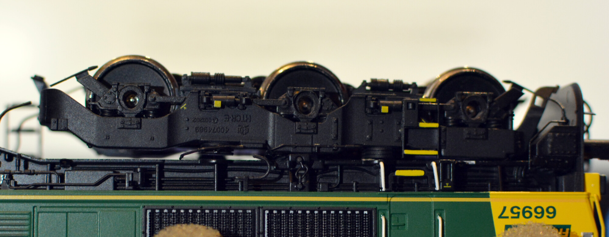
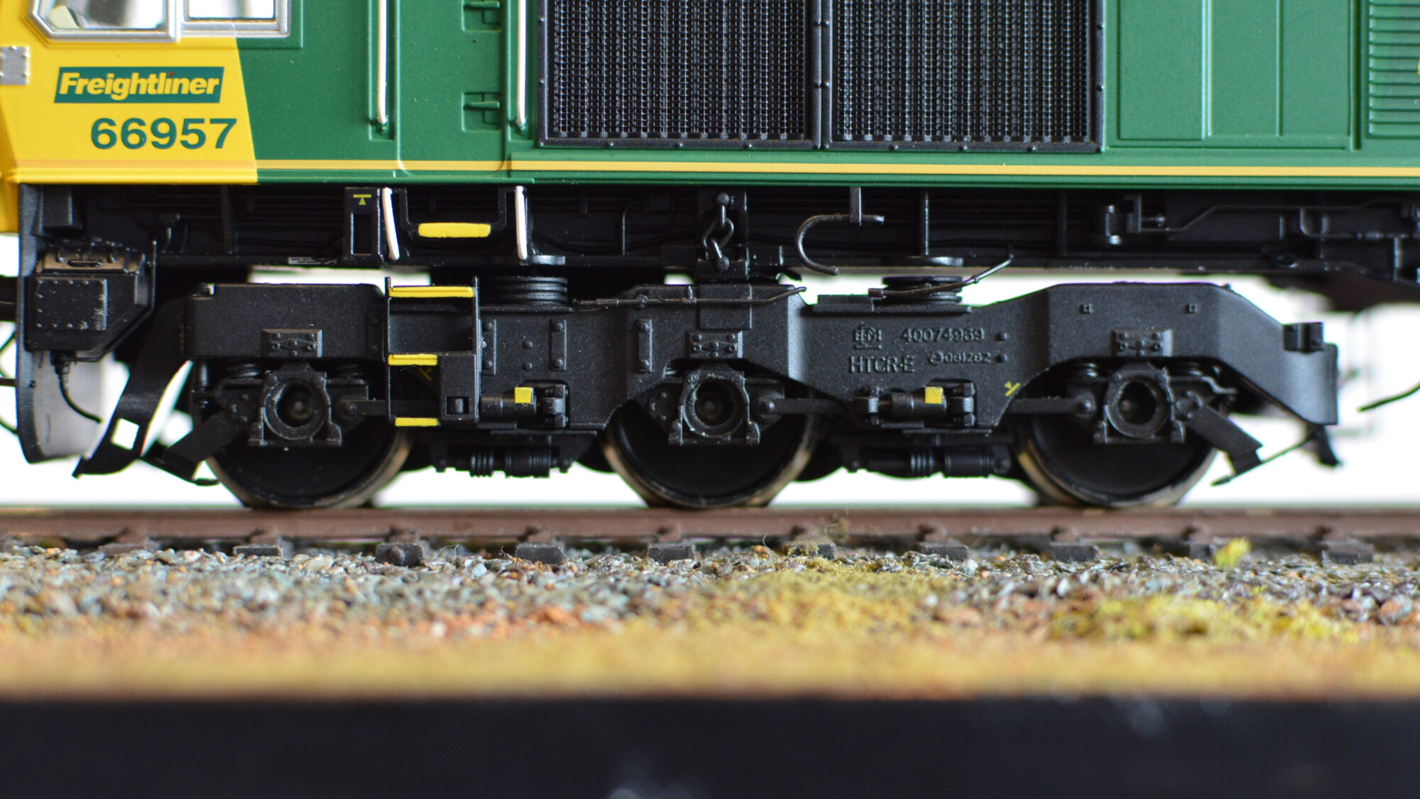
This isn’t a problem per-se, but I’ve noticed that the end of the axleboxes do tend to protrude from the bogie frames a bit too much, which does spoil the effect a little unfortunately. The loco needs to be able to negotiate 2nd-radius (438mm) curves, so this extra play is necessary, but I don’t plan on running the loco on anything less than fourth-radius (572mm) curves. In light of this, I’ve decided to shorten the axleboxes by about 0.5mm, resulting in a 1mm total decrease for a complete wheelset, which should make the completed bogies look even better than they do now, whilst (hopefully) not affecting performance.
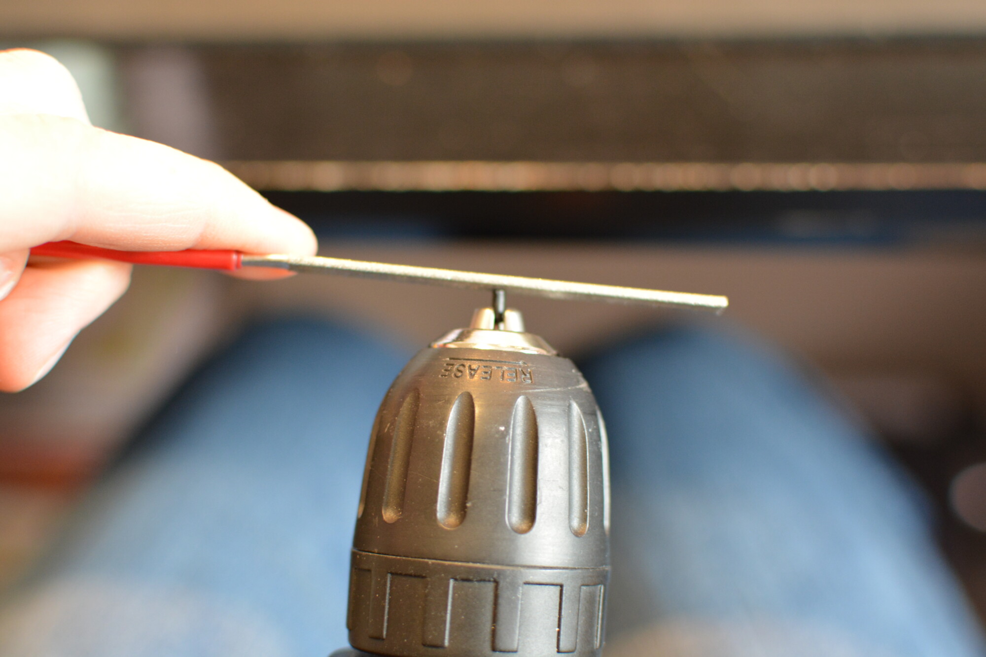
To shorten an axlebox, I (very carefully) secure it in the jaws of a cordless drill’s chuck, making sure to align it as vertically as possible, and taking care not to crush it. It’s rather fiddly to get right, as the only bit to grip on is the visible end of the axlebox, so take care! Once secure, I ran the drill at full speed and very gently pressed a flat needle file onto the end.
The reason I chose this method is that the axlebox needs to have as straight a face as possible, as any angle here will cause it to not sit perpendicular to the wheel, which will make it wobble even worse than when I started! Turning it using a drill means even if I’m not holding the file perfectly straight, I should still get a good result.
Putting it back together
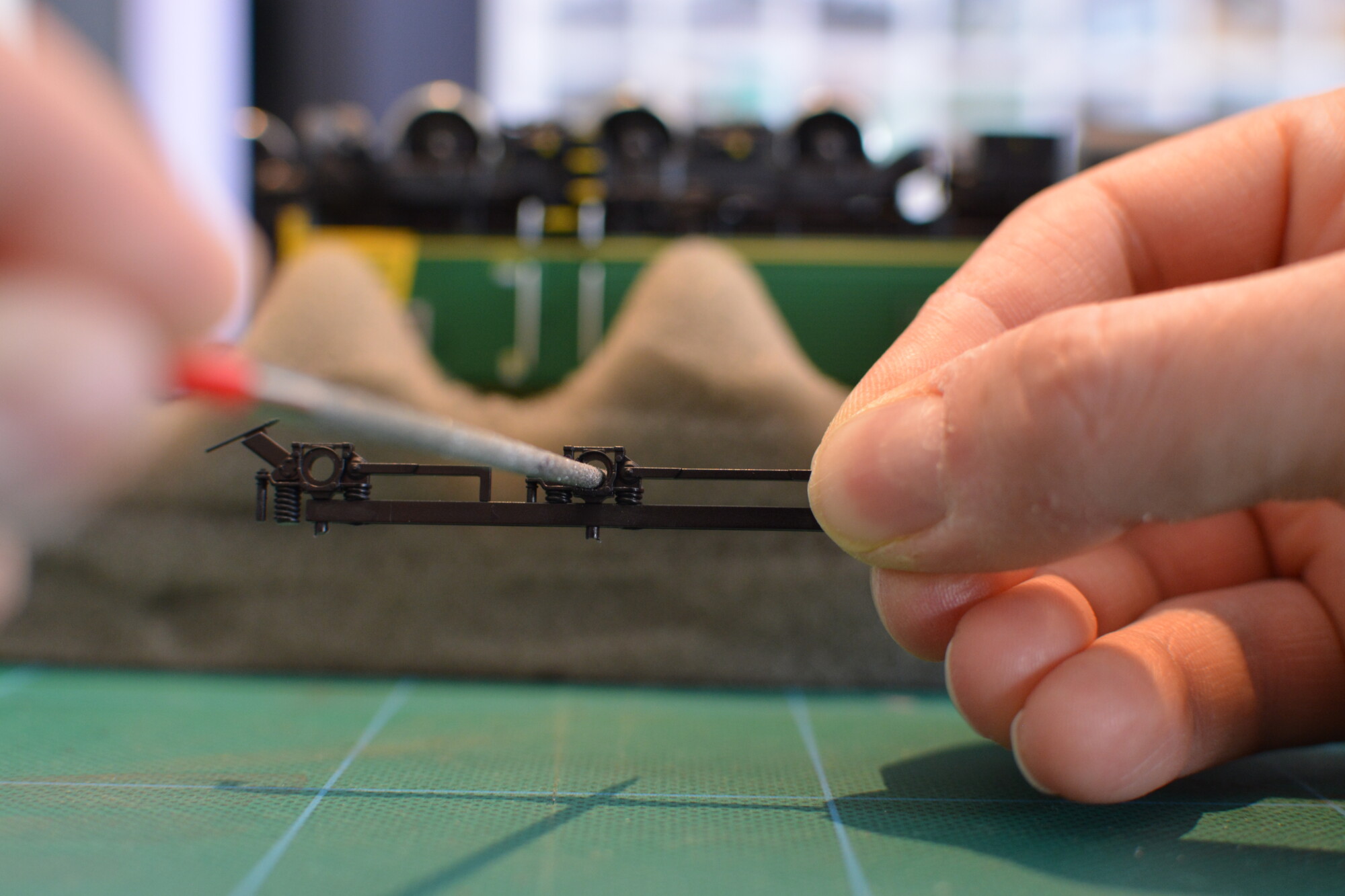
Once the axleboxes have been turned down, it’s time to re-assemble the bogies. First I re-inserted the inner bogie frames, making sure the axles are nice and centred when the locomotive is the right way up.
Finally, I re-fitted the shortened axleboxes, attaching them with a tiny drop of superglue. All it needs is the tiniest drop to hold the axlebox on. I used a slightly longer-setting cyanoacrylate that gives me about 20 – 30 seconds before it goes off. This gave me time to fit an axlebox, transfer the loco to the rolling road and run it at low speed. Whilst it was running, I used a small screwdriver to adjust the axlebox so it was no longer wobbling.
In summary
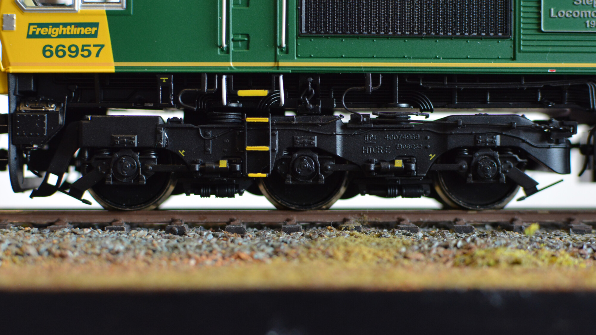
Whilst it’s a shame that the model is a bit let down by this issue, it is possible to remedy it with a few hours’ work. Of course whether you think this is worth the time and effort is up to you, but I’m certainly glad with the result. My 66s now run very nicely, with much less wobble than before, and the axleboxes stay centred whilst they rotate.