
I’ve recently acquired a rather nice little Hornby Terrier loco. It’s one of the ex-Dapol tooling models, so while it’s not up to the standards of the more modern Hornby offering, it’s still a reasonable model that I’d like to get running. As it’s one of the old models, it doesn’t come with a DCC socket, and fitting a chip might be a challenge due to the severe shortage of space inside the body! I’ve therefore decided to forego the Zimo MX600 decoder I normally use (in my opinion the best decoder for the price on the market by far), and use it’s baby brother, the MX617F.
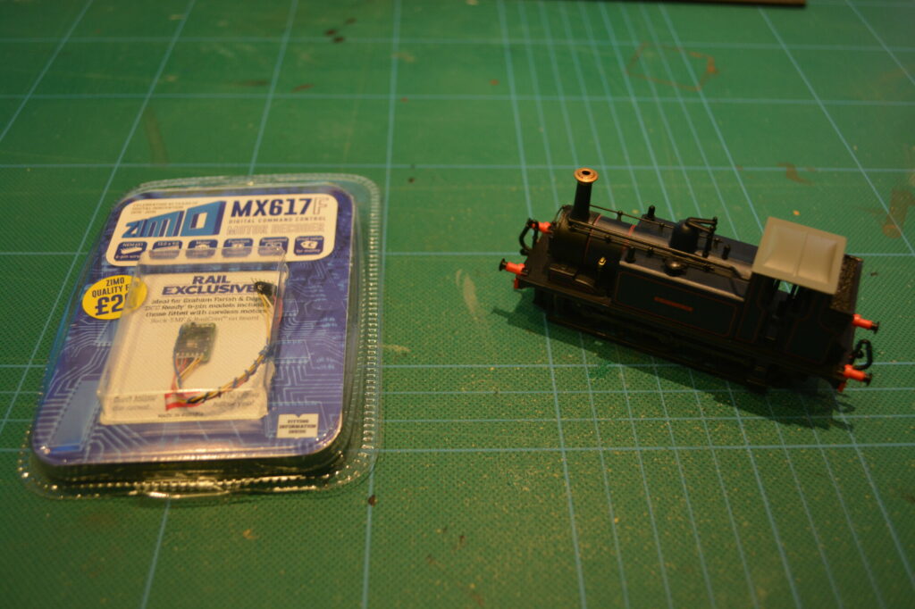
This model offers the same excellent motor control as the rest of the range, but with a reduced peak and sustained current output. This will not be a problem, as the motor in the model will not draw that much.
Even with such a small decoder (this one measures just 13x9x2mm), finding a place to fit it will still be a challenge. Let’s open it up!
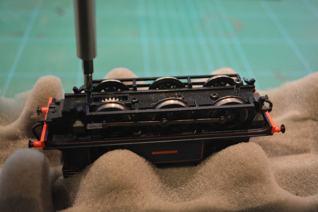
With the body off, we can see where we might be able to place the decoder. There is a small slot in the bunker at the back, above the grey metal weight, but I decided against this, since this would mean running the decoder harness through the cab, where it would be on display.
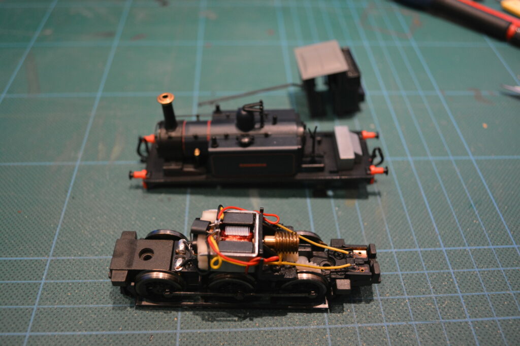
Having measured the space inside the motor cavity, I determined that there would just about be enough space for mount the decoder longitudinally on top of the motor, as shown below:
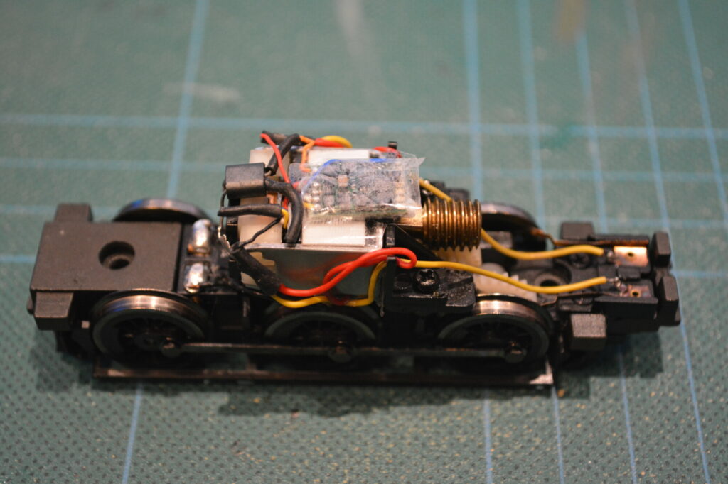
Before mounting the decoder, I glued 0.5mm plasticard shims to the dark grey magnets. This ensures that the motor armature will not hit the underside of the chip as it rotates. The decoder itself is hard-wired to the chassis, as there is simply no space for a socket of any kind!
Before I re-assembled the loco, I took the chance to fill up any spaces I could find with lead to improve electrical pickup and adhesion. I added one strip in the aforementioned slot in the bunker, and one strip in the motor cavity, right above the worm gear. They’re not huge weights, but every little helps.

This was a pretty satisfying decoder install, since this loco has been sitting on my shelf for months. Now I can finally run it! The next step is to fit Kadee couplings to it so it can actually pull something.