Now the boards have been prepared, it’s finally time to start laying track! I’ll be using Peco code 75 for this project, with the following modifications:
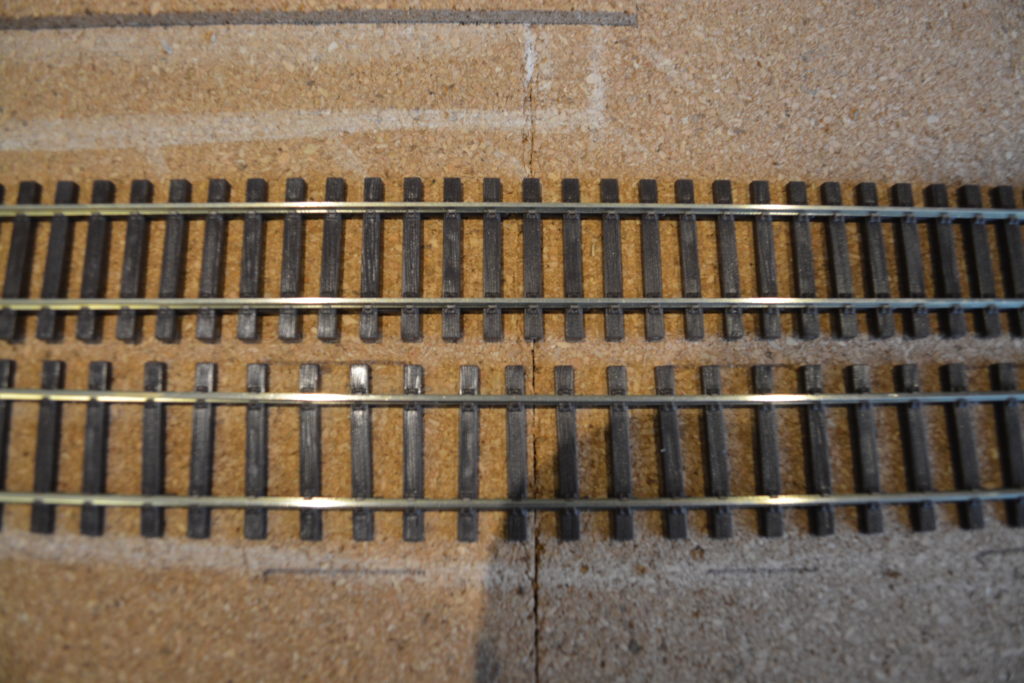
- I’ll be re-spacing the sleepers to look more prototypical. I’ve recently seen this done on the excellent Everard Junction Youtube channel, and it really does improve the look of the track. This is for plain track only – it’s a bit tricky to re-space sleepers on points! In real life, sleeper spacing on points tends to be tighter anyway, so this shouldn’t be too much of an issue.
- I’ll also be cutting off the tie-bar horns to make the points look more like the real thing.
- The links that join the point frogs to the rest of the point will be removed, so that we can control the feed to the frog from a polarity switch built into each point motor.
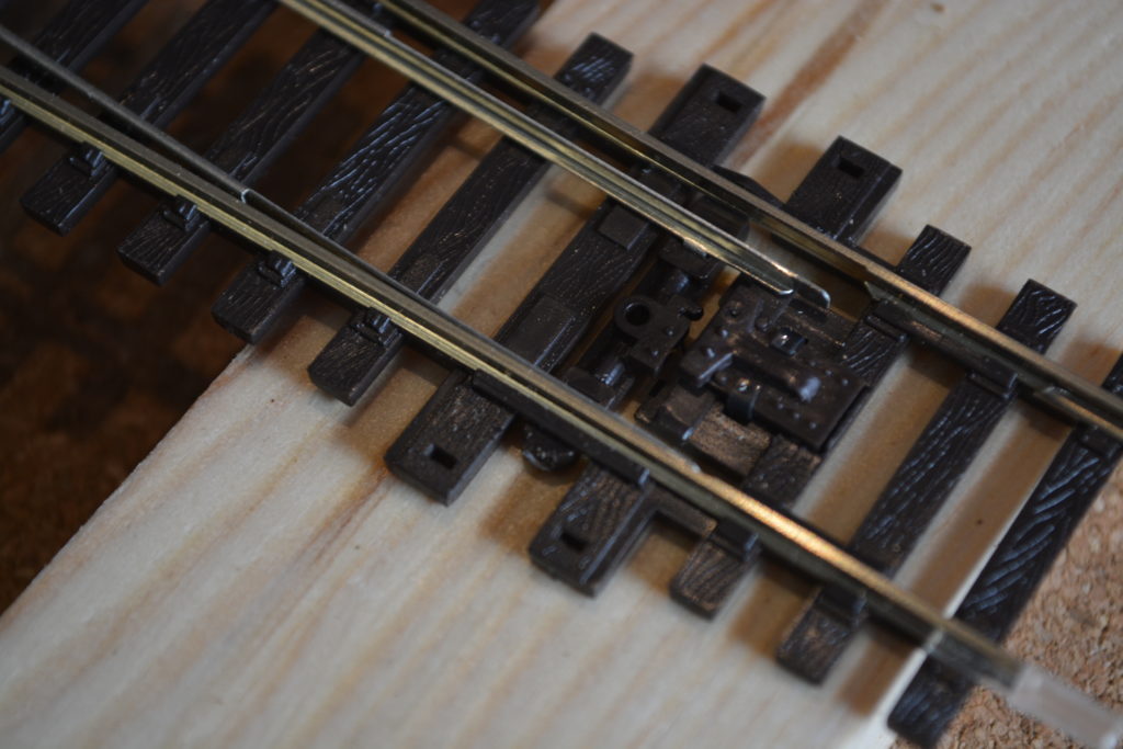
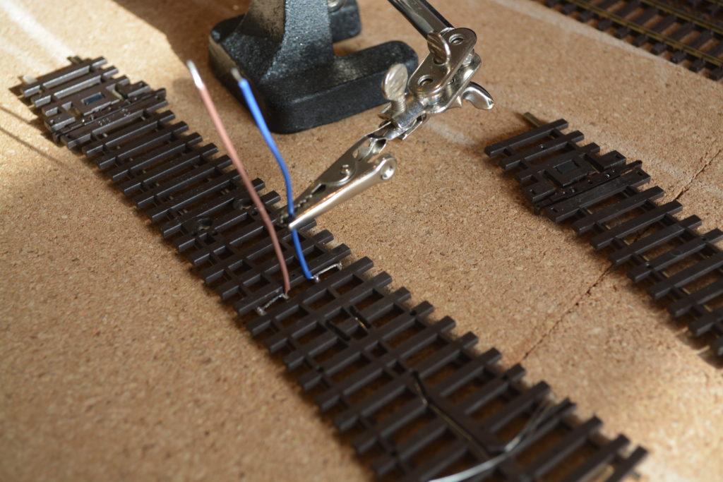
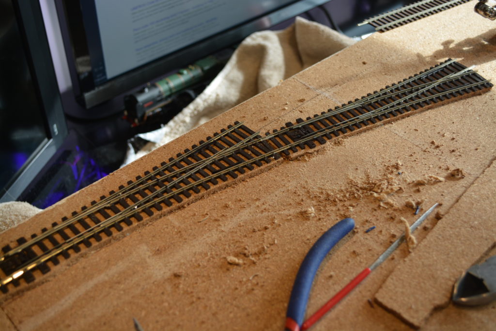
The first bit of track to be laid is the first (leftmost) turnout in the station. Once the frog links and tie-bar horns have been removed, the next step is to solder dropper wires to every piece of track that will be laid – every individual rail will have it’s own feed, so that we don’t have to rely on rail joiners to conduct current.
The turnout is then put in place, and holes for the the droppers and frog feed are marked and drilled. An 8mm hole for the point motor rod is also drilled. I then applied a small amount of wood glue to each sleeper (keeping the area around the tie-bar clear of glue), refitted the turnout and weighted it down with some heavy books.
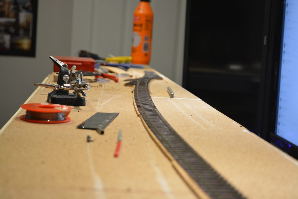
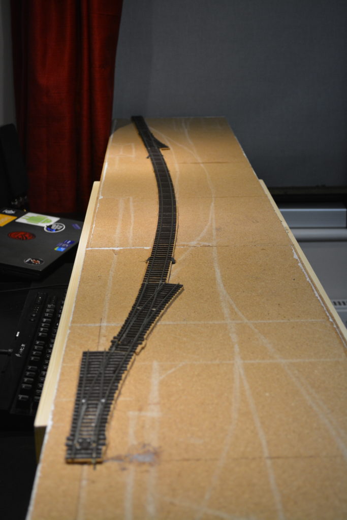
After these two turnouts, the next bit of track to be laid was the most important one to get looking right – the platform line. The tricky thing here was getting the curve to look good (since it starts by following the curve from the wye turnout and gradually straightens).
When laying plain track, I used a scalpel with an old blade to cut the webbing between each sleeper. I then re-spaced the sleepers using a steel rule to a distance of 85mm per every 10 sleepers.
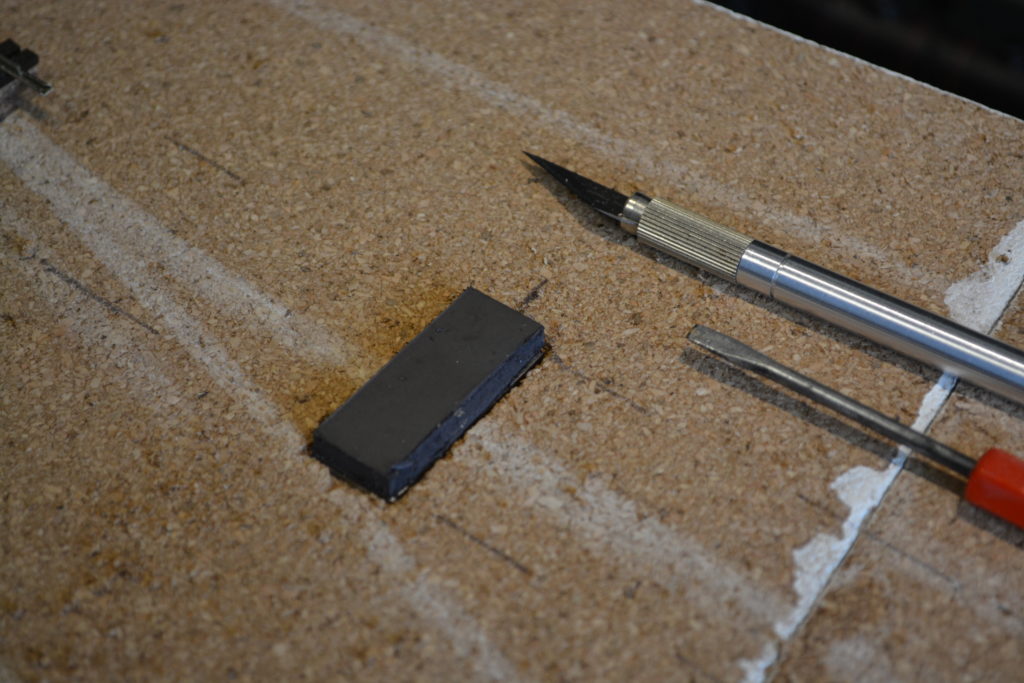
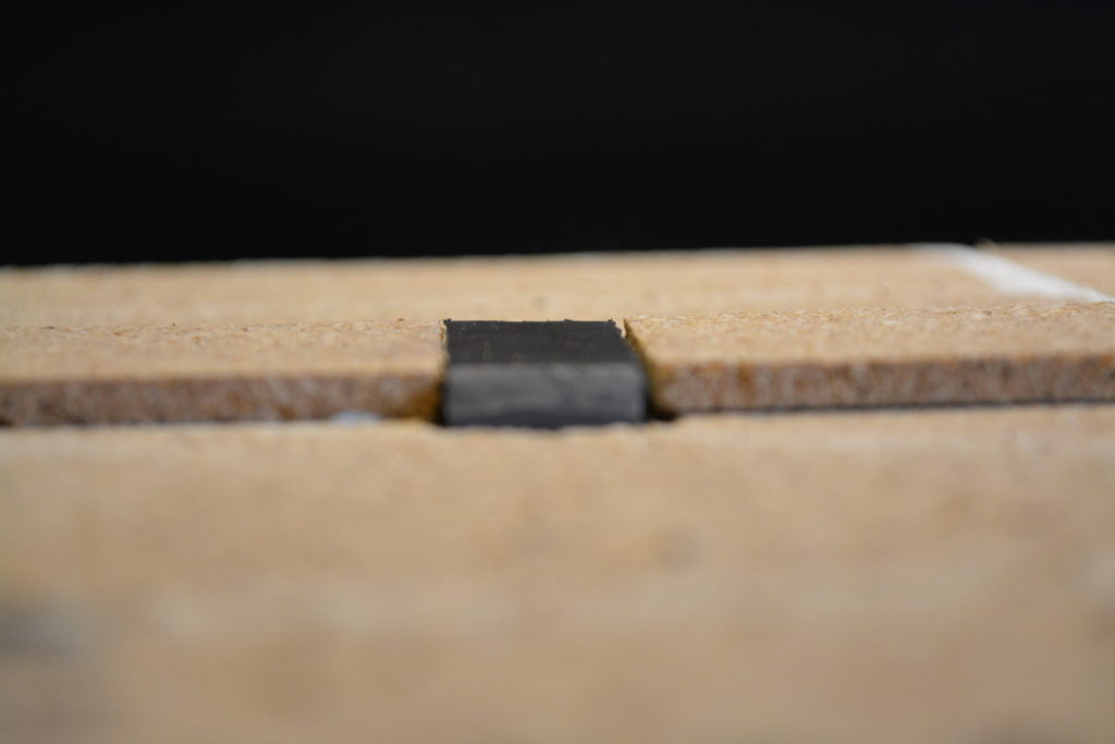
Kadee uncoupling magnets
I’ve also been fitting Kadee uncoupling magnets at strategic points under the track. These consist of a soft rubbery magnetic plate, about 50mm long, and a 1mm steel plate of the same size that increases the magnetic field. Since they are quite long, I have cut each one into 3.