
At the heart of every DCC model railway lies the so-called command station. This is a device that takes commands from a handset, computer, or other input device, and converts them into DCC commands which are then sent to a locomotive or accessory via the DCC bus. If you want to read more about what a command station is, DCC Wiki have a good overview here.
Some background
It’s quite common to see command stations and boosters attached permanently to a layout, often mounted on the underside of the baseboard. I’ve chosen to build a dedicated, portable, control unit instead so that I can use with Weybourne, the layout I’m building at the moment, and any other layouts I build in the future.
In this post I’ll talk about why I chose to build rather than buy, some of the key design decisions I made along the way, and show the construction process. This will actually be the second command station of this type I’ve built, as this particular one will be going to Dad for him to use for layout control. I’ll be following a very similar design to the one I built for myself two years ago, with some improvements.
I’ve chosen to go with the Model Electronic Railway Group (MERG)’s kit-built DCC system for two reasons:
- Cost. For about £150, I can build a system that is functionally equivalent to an off-the-shelf system costing three times as much.
- It’s more fun to build it myself. I’ll learn how it actually works, and it will be easier to fix if something goes wrong.
The MERG system
I’ve been a member of MERG for a couple of years now. In addition to their excellent DCC and CBUS kits (more on these later), they also offer advice on most things electronic, produce technical bulletins and journals, and hold regular meetings around the country. I wholeheartedly recommend joining them if you are interested in any form of model railway electronics, be it coach and building lighting, layout control or even signalling and automation systems.
I’ll actually be building two things: The actual control unit (containing both a command station and a power booster) and a control handset for driving locomotives. All the electronics kits will be coming from MERG, and other items, such as connectors, cabling and the enclosure for the control unit will be ordered from one of the big electronics suppliers such as Farnell or Rapid. I’ll be covering the control unit in this post, and the handset in a future post.
It’s worth pointing out that when I say control unit, I am referring to the box that contains both a DCC command station and a DCC booster. A pure command station typically does not provide much power to the track (normally less than one amp), so there are almost always paired with a booster that takes the output signal from the command station and boosts it up to between three and ten amps. In fact, it’s very rare to see an actual standalone command station these days – they are almost always sold attached to some form of booster.
Solution design
The block diagram below shows what I’ll be building. The large box represents the control unit itself. At the rear of the unit (on the left side of the diagram), there is the DC power supply input, the two track connections and the USB input. This control unit will take full advantage of the MERG system’s ability to simultaneously drive a programming track and a main track, meaning that I will be able to drive a layout using track connection 1, whilst programming a locomotive on track connection 2.
At the front of the unit (on the right of the diagram), there will be a pair of RJ22 CBUS connectors, used for connecting up MERG control handsets or other accessories, and a set of status LEDs for power status, track power and short circuit indication.

CBUS – the MERG control system
Before I go any further, it’s good to understand what CBUS is, and how it will be used in the control unit. CBUS is a control system developed by MERG that is based on the popular automotive CAN bus. Physically, it consists of a single twisted pair of wires for data, and an additional pair of wires for supplying 12V power to modules. Up to 110 modules can be connected together, although this can be increased significantly with the addition of repeaters. At the protocol level, CBUS modules can send send (or produce) and receive (or consume) CAN frames, which are small packets of data that contain commands and events.
A simple example of a CBUS message is a handset sending a speed message to change the speed of a locomotive: The speed knob is turned on the handset, which then sends a CBUS message containing information such as the locomotive address, the direction and speed. The command station receives this message, parses it and issues a corresponding command on the DCC bus. This command is then decoded by the locomotive.
In my system, the control handsets, the USB interface and a turnout control panel will be producing CBUS events, and the command station will be the sole consumer of events. The turnout control panel will be covered in a separate post.
In the block diagram above, track connection 1 contains not only the main DCC output, but also the CBUS as well. This means that I can add CBUS panels to a layout to allow me to plug in control handsets directly to the layout, rather than the control unit, which may not be conveniently located in some cases. The plan is to have a single 6-core cable that carries both the DCC and the CBUS to a layout to make connecting to the layout as simple as possible.
Parts list
- 1x MERG DCC Command Station (CANCMD – kit 92).
- 1x MERG DCC Booster (NB1B – kit 59).
- 1x MERG USB Interface (CANUSB4 – kit 80A).
- 1x MERG RJ22 Connector kit (horizontal) (kit 93H).
- 1x Hammond aluminium enclosure (1455T2201 – 223x160x52mm).
- 1x Switchcraft 2.5mm Panel Mount Power Socket (712A).
- 1x SCI SPST Rocker Switch (R13-112A2).
- 1x Lumberg 3-pin DIN socket (KFV30, DIN standard 60130-9).
- 1x Lumberg 6-pin DIN socket (KFV60, DIN standard 60130-9).
- 3x Signal Construct panel-mount LEDs (Red SMQD060, Yellow SMQD061, Green SMQD062).
- 16x Self-adhesive PCB stand-offs.
- A couple of strips of 2.54mm spaced pin headers and plugs.
- Some 2.54mm spaced stripboard.
- Ribbon wire (various gauges – larger 2-core for primary DCC, smaller 4-core for CBUS and secondary DCC).
- Heatshrink tubing.
Getting started
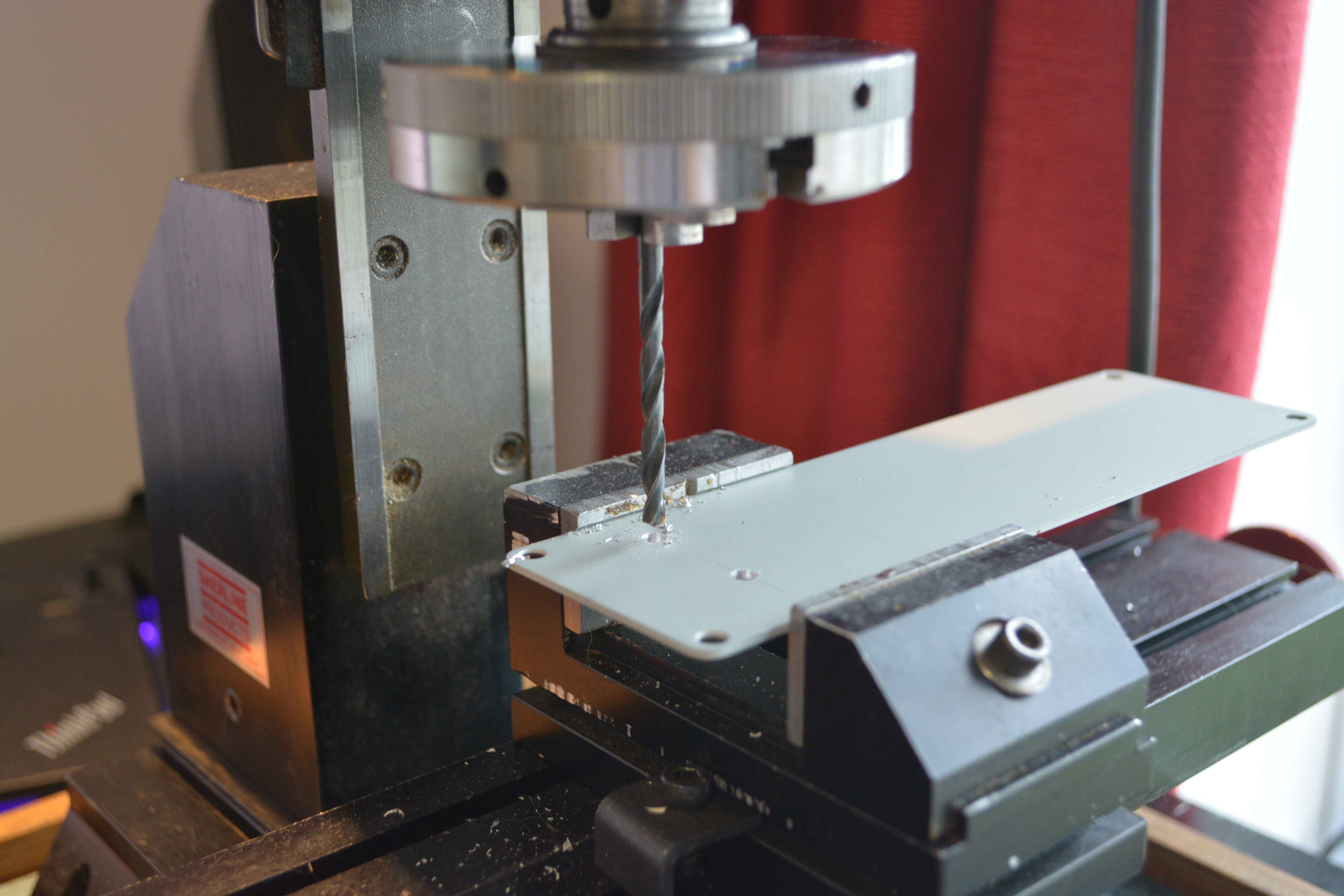
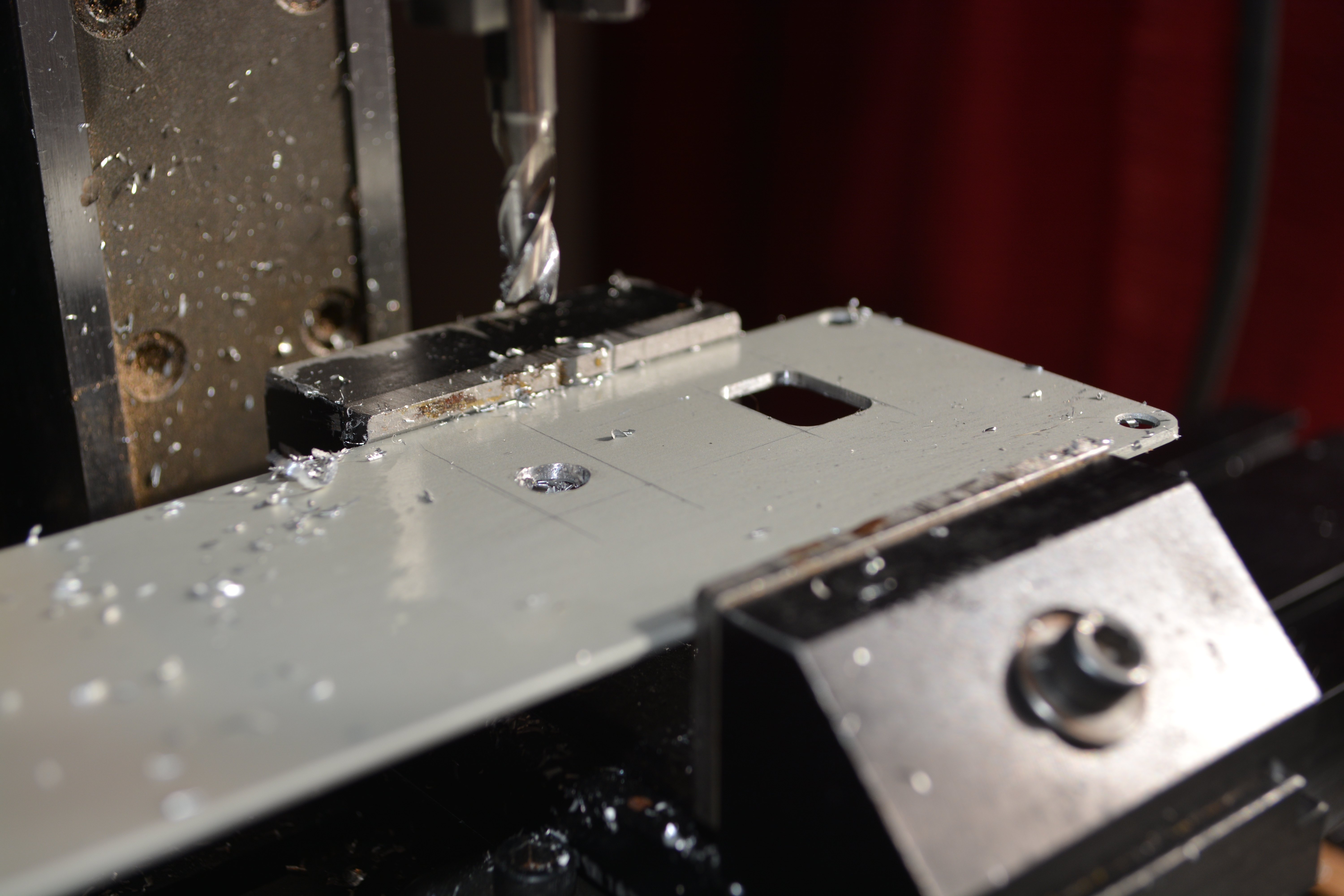
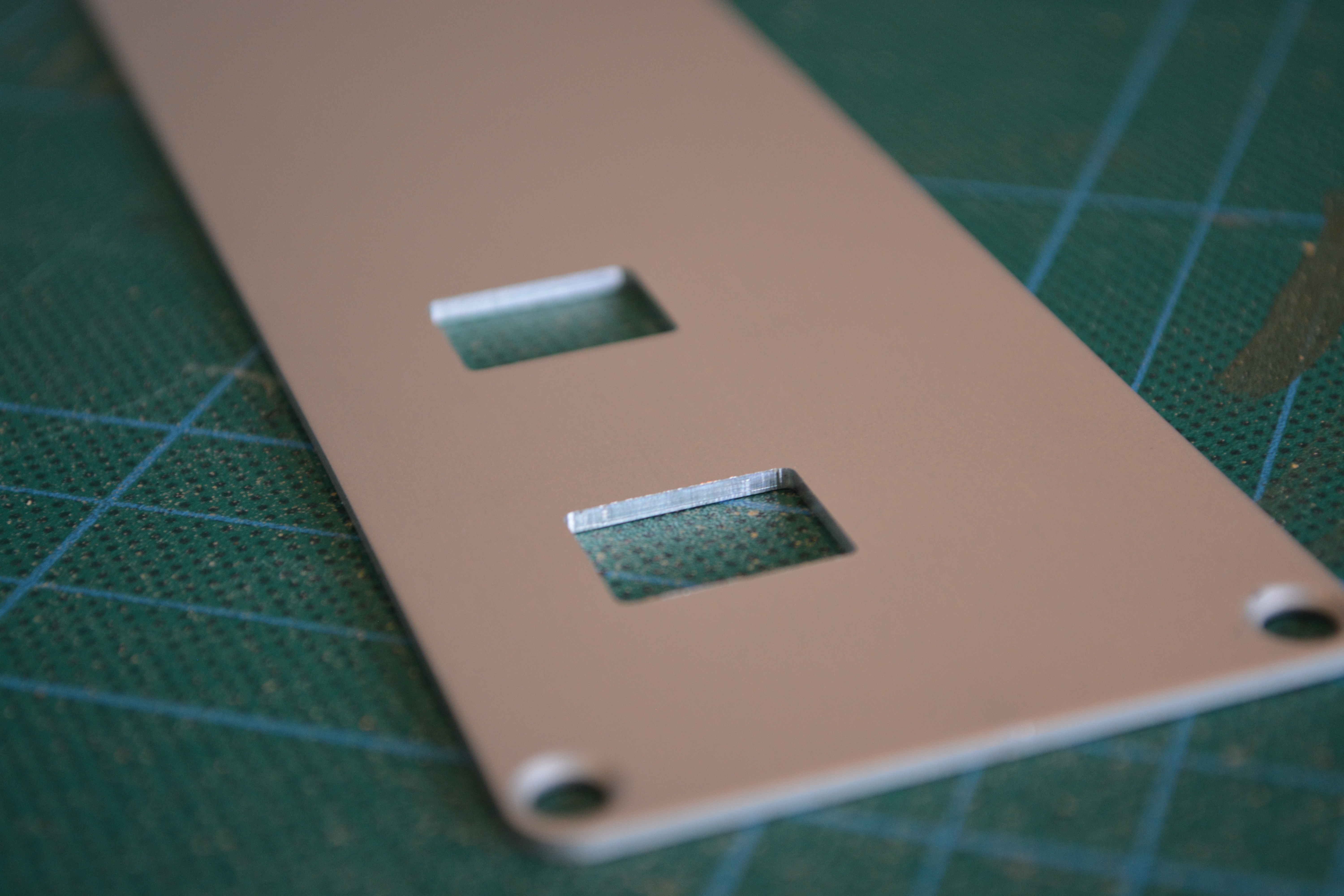
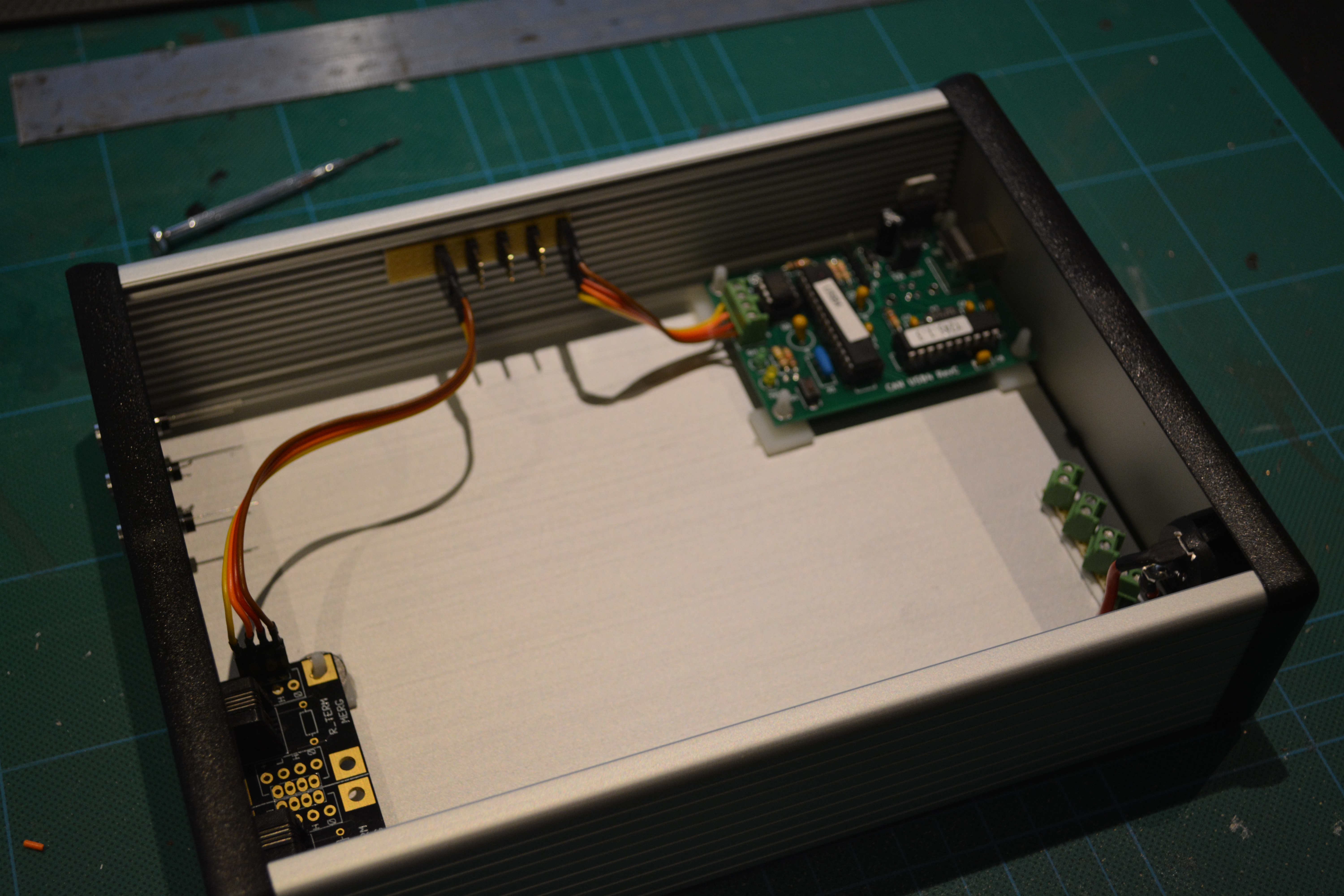
The first job is to mill the various holes that I’ll need in both the front and rear enclosure faceplates. In the rear there will be holes for the power socket, power switch, primary and secondary outputs and USB connector, and in the front there will be holes for the 2 RJ22 CBUS connectors and the 3 status LEDs.
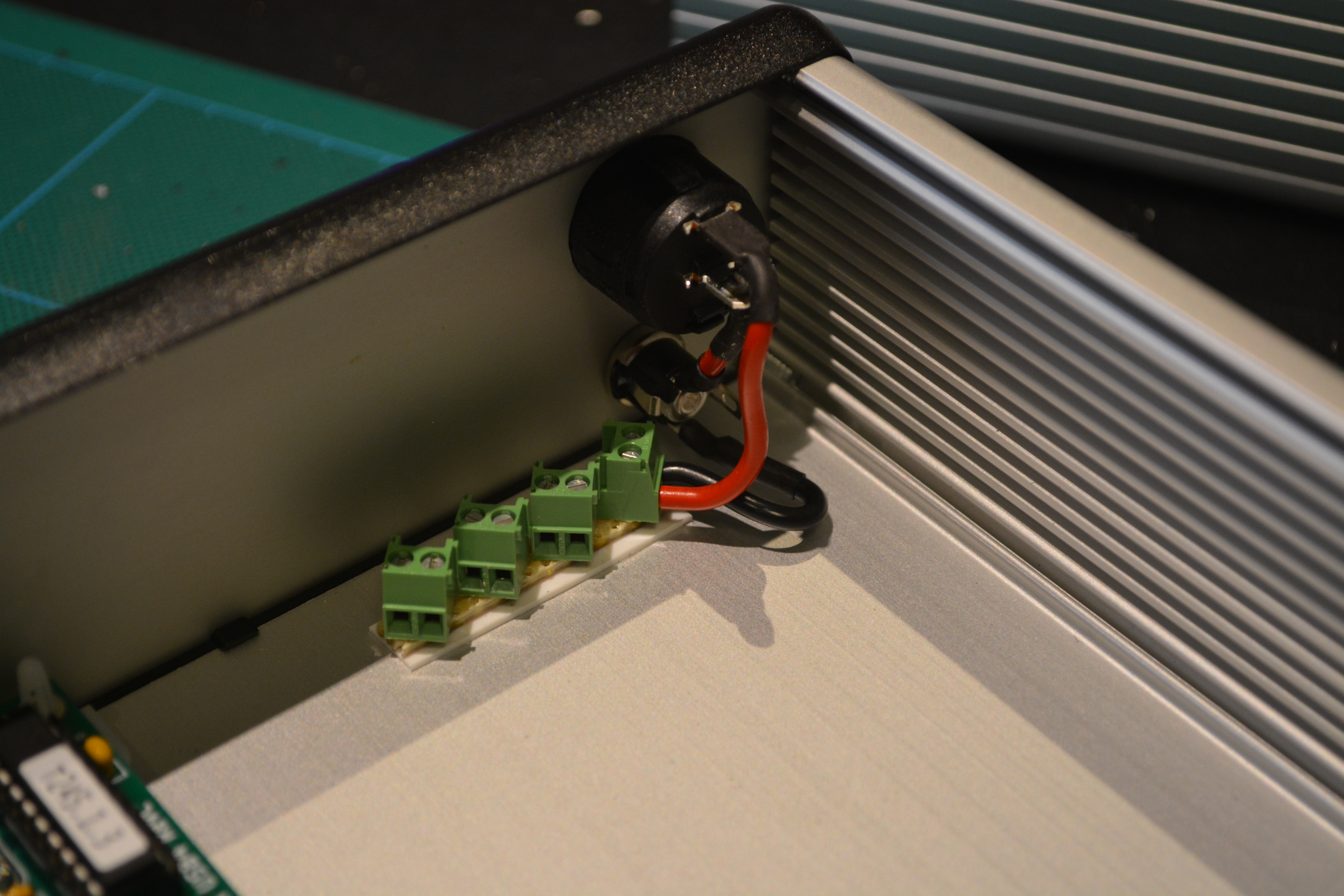
Power connections
The next step is to install the power system in the enclosure. This is pretty easy, since only the command station and the DCC booster will need 15VDC.
Installing the PCBs
Building the command station, DCC booster, USB interface and CBUS interface was a relatively straightforward task – the instructions that MERG provide take you through the process step-by-step, starting with the shortest components and working up to the taller ones. All the soldering is through-hole, meaning that you place the component through holes on the PCB and solder it from the back. A good soldering station is essential, and a helping hand tool to hold the PCB at various angles is also very useful. Once soldering is complete, the instructions guide you through a set of basic electrical tests to make sure there are no shorts or dead joints, and after these pass you then install the various microcontrollers.
Now the four PCBs are built and tested, it’s time to install them in the enclosure. This is simply a case of inserting a self-adhesive PCB stand-off in each of the four corner holes in the PCB, and then pressing the PCB firmly into position.
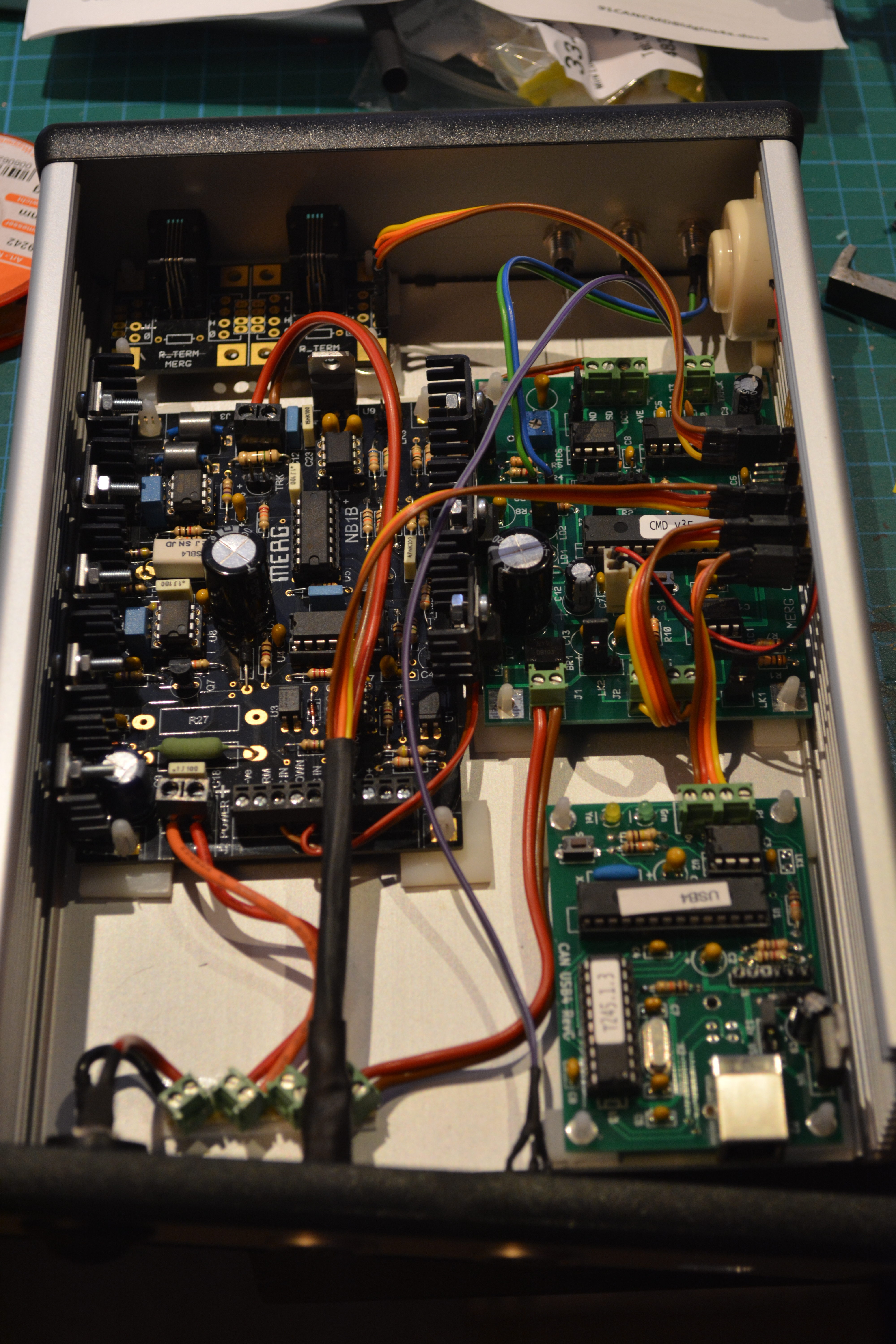
Connecting up and test running
With the control unit now assembled, it’s time to test it. To do this, I connected it to my PC via USB, and once the USB driver for the CANUSB4 had installed (this is automatic on Windows 10 since the driver is a standard USB serial port driver), I launched JMRI DecoderPro.
I’ll be covering JMRI in a separate series of smaller posts, but basically it’s an application that runs on a PC or Mac (or even something smaller like a Raspberry Pi) and communicates with a DCC Command Station. This allows you to drive trains and operate accessories from the computer, or even connect other devices, for example smartphones, to control things from there. For the purposes of this article, DecoderPro is the part of JMRI that is used for programming locomotives. It has become popular for this task since programming CVs using a handset is rather tedious and prone to errors. DecoderPro takes (almost!) all the pain out of of programming locos, and also makes programming more complex compound CVs a piece of cake. It even has basic throttle control, so you can drive your locos to test the changes you’ve made.
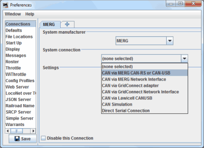
The first step is to tell JMRI what type of command station it should connect to. The good news is that the MERG system is fully supported by JMRI, so this is simply a matter of opening up the Preferences, going to the Connections tab, and choosing MERG from the System manufacturer drop-down. After this, I then selected CAN via MERG CAN-RS or CAN-USB as the System connection, set the COM port to the port provided by the CAN-USB, and clicked on save. At this point I needed to restart DecoderPro for the changes to take effect.
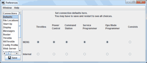
Once the connection has been setup, and DecoderPro has restarted, all I had to do was go back to Preferences, and in the Defaults tab, set all the options (except Consists) to MERG. This tells JMRI what command station to use for each function, in the event there are multiple command stations connected.
With the unit connected, I performed the following tests to check the unit was working properly:
- Read CV values from a locomotive on the programming track.
- Write CV values to a locomotive on the programming track.
- Control a locomotive on the main track.
All tests went as planned – so the unit is ready for use! One test that I did not perform is testing of turnout control. This is because the MERG command station firmware has only recently been upgraded with the ability to control pure DCC accessories – up until this change it was only capable of sending commands to CBUS accessories, something I have found to be a limitation in the past! I will write a post soon when I get round to upgrading the firmware on the command station.
Final thoughts
All in all, I’m very pleased with the unit I’ve built. Obviously a lot of the credit must go to the excellent kit design from MERG – they really are easy to put together, considering what the assembled units can do. The unit itself has proven reliable – I’ve been using it for over 2 weeks now and it’s been rock solid.
Having the milling machine made cutting the holes in the front and rear panels much easier, and resulted in a much higher quality finish than if I’d drilled and filed the holes by hand.
The Lumberg DIN connectors I used for the two track outputs are excellent – they give a nice secure connection every time thanks to the screw locking rings built into the outer casings. In future posts I’ll be covering how I use the same connectors on my layouts.
The next task for this control system is to build a MERG CANCAB handset that I can use to control locomotives. After that I’ll be building a turnout control panel for Weybourne using the MERG CANPAN unit.